Drill bit apparatus and method of manufacture of same

a technology of drill bit and machine tool, which is applied in the direction of manufacturing tools, twist drills, wood boring tools, etc., can solve the problems of insufficient self-feeding of conventional self-feeding drill bits, and inability to produce smooth workpiece bores

Inactive Publication Date: 2003-11-25
QUICK TURN MFG
View PDF19 Cites 51 Cited by
  • Summary
  • Abstract
  • Description
  • Claims
  • Application Information

AI Technical Summary

Benefits of technology

It is a second object of the present invention to provide a cutting apparatus having a low manufacturing cost and low production cost.
It is a further object of the present invention to provide a cutting apparatus which exhibits extended durability, thereby minimizing tooling downtime.
Another object of the present invention is to provide a cutting head that can maintain the sharpness of the cutting edges, so that chip formation can be properly controlled, and so that the bore surfaces can be of suitable surface finish.
A further object of the present invention is to provide a channel for efficiently expelling chips formed during the drilling operation.
Each cutting vane includes a first cutting edge which extends perpendicular to the axis of rotation and is provided for removing workpiece material, a second cutting edge which extends parallel to the axis of rotation and is provided for forming a substantially smooth workpiece bore, and a channel for facilitating the expulsion of removed workpiece material away from the first cutting surface as the drill bit passes through the workpiece.

Problems solved by technology

However, conventional self-feeding drill bits fail to produce smooth workpiece bores.
Further, many conventional self-feeding drill bits chip the surface of the workpiece which remains.
In other words, most conventional self-feeding drill bits cause chipping of the workpiece surface outside the circumference of the workpiece bore as the drill bit enters the workpiece.
In such a case, most conventional self-feeding drill bits are inadequate because after the drill bit is withdrawn, uncut material remains at the bottom of the cavity.
However, most conventional self-feeding drill bits are inadequate for producing cavities, because when the drill bit is withdrawn from the cavity, uncut material typically remains around the hole created by the screw.
Therefore, such conventional drill bits produce cavities having an unsuitable finish.

Method used


Image

  • Drill bit apparatus and method of manufacture of same
  • Drill bit apparatus and method of manufacture of same
  • Drill bit apparatus and method of manufacture of same

Examples


first embodiment

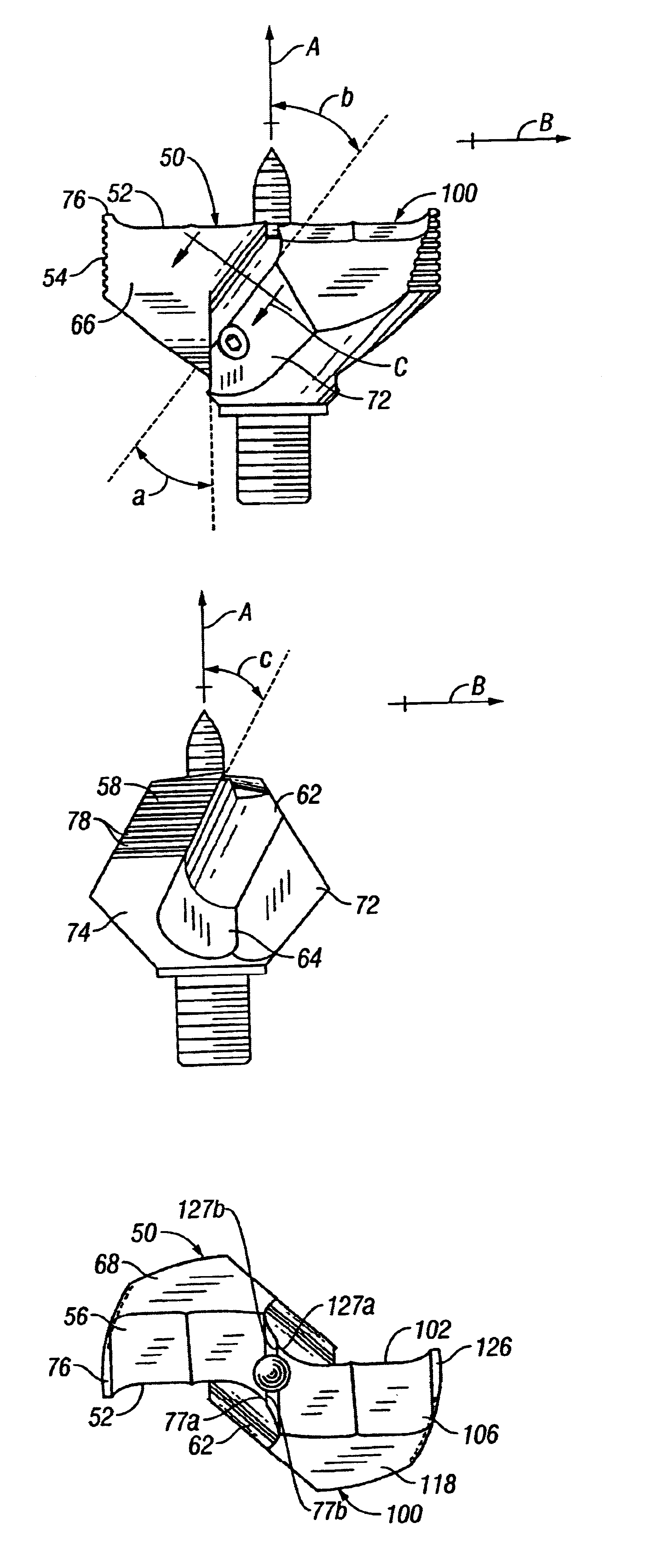
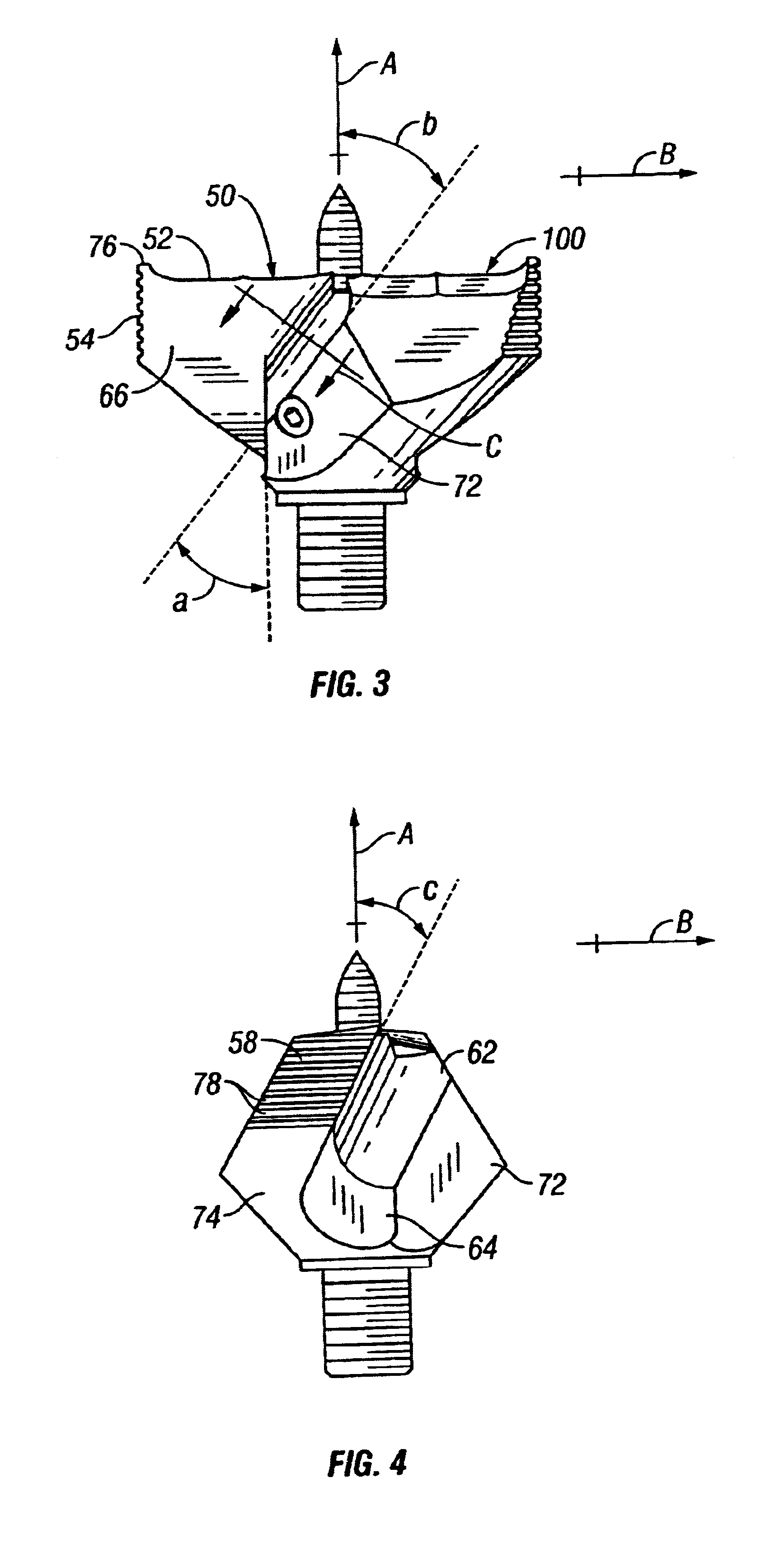
the cutting head 32 is shown and described in FIGS. 3 through 9. This embodiment is adapted to produce a workpiece bore which has a diameter of approximately 1.75 inches. As shown in FIG. 3, the cutting head 32 of the first embodiment includes a first cutting vane 50 and a second cutting vane 100. The first cutting vane 50 and second cutting vane 100 are substantially identical. Further, the cutting vanes 50,100 are oriented about an axis of rotation, defined by line A, so as to be radially positioned 180 degrees apart.

The first cutting vane 50, as shown in FIGS. 3, 4, 5, 6 and 7, includes a first cutting edge 52, a second cutting edge 54, an upper surface 56, an outside surface 58, a first inside surface 62, a second inside surface 64, a front surface 66 which extends substantially parallel to a trailing surface 68, and a grasping surface 72. The first cutting edge 52 is formed by the intersection of the upper surface 56 and front surface 66. The second cutting edge 54 is formed by...

second embodiment

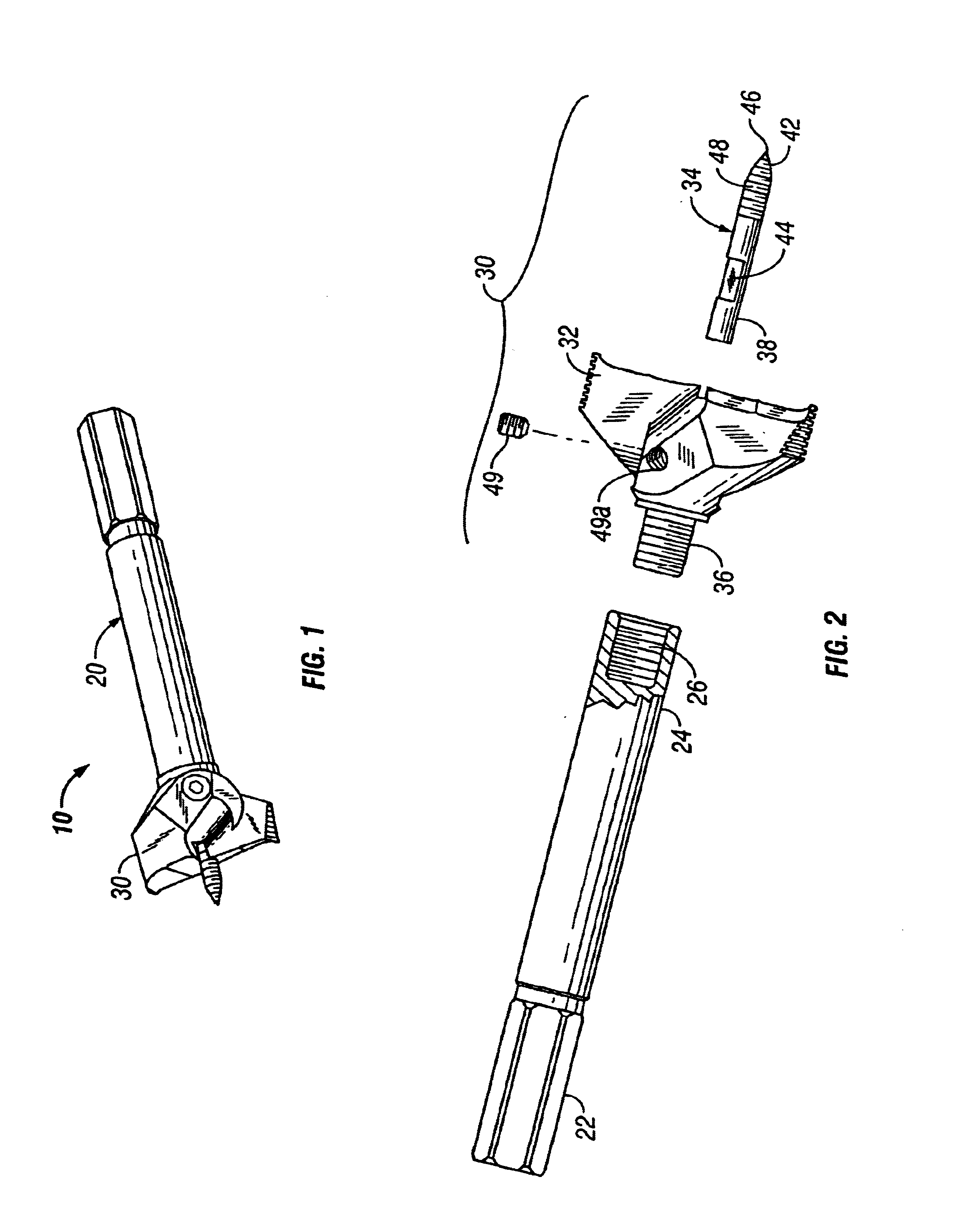
the drill bit head 30 is shown and described in FIGS. 10 through 16. This embodiment is adapted to produce a workpiece bore which has a diameter of approximately 0.875 inches. As shown in FIG. 10, the cutting head 32 of the second embodiment includes a first cutting vane 150 and a second cutting vane 200. The first cutting vane 150 and second cutting vane 200 are substantially identical. Further, the cutting vanes 150,200 are oriented about an axis of rotation, defined by line A, so as to be radially positioned 180 degrees apart.

The first cutting vane 150, as shown in FIGS. 10 through 14, includes a first cutting edge 152, a second cutting edge 154, an upper surface 156, an outside surface 158, an inside surface 162, a front surface 164 which extends substantially parallel to a trailing surface 166, a grasping surface 168, a substantially flat first side surface 172 and a rounded second side surface 174. The first cutting edge 152 is formed by the intersection of the upper surface 1...


PUM

PropertyMeasurementUnit
acute angleaaaaaaaaaa
anglesaaaaaaaaaa

Abstract

A drill bit for use in association with a power or hand drill comprising a drill bit head and shaft. The drill bit head includes a drill bit cutting head and a guide point. The drill bit cutting head includes a first and a second cutting vane. Each cutting vane includes a first cutting edge which extends perpendicular to the axis of rotation and is provided for removing workpiece material, a second cutting edge which extends parallel to the axis of rotation and is provided for forming a substantially smooth workpiece bore, and a channel for facilitating the expulsion of removed workpiece material away from the first cutting surface as the drill bit passes through the workpiece.

Description

1. Field of the InventionThe present invention is directed in general to drill bits and boring equipment, and more particularly to a drill bit apparatus and corresponding method of manufacturing the same.2. Background ArtDrill bits have long been used in the machining and building arts. Generally, drill bits have surfaces which engage and remove material from a workpiece, thereby creating a workpiece bore. Self-feeding drill bits, as opposed to most spade bits or auger bits, are generally preferred because they cut workpiece bores faster, require less axial force to operate, and can produce workpiece bores which have larger diameters. However, conventional self-feeding drill bits fail to produce smooth workpiece bores. Further, many conventional self-feeding drill bits chip the surface of the workpiece which remains. In other words, most conventional self-feeding drill bits cause chipping of the workpiece surface outside the circumference of the workpiece bore as the drill bit enter...

Claims


Application Information

Patent Timeline
Patent Type & Authority Patents(United States)
IPC IPC(8): B27G15/00
CPCB27G15/00Y10T408/03Y10T408/905Y10T408/909Y10T408/902Y10T408/9065
Inventor REMKE, TONY J.OLAS, JOHN
Owner QUICK TURN MFG
Why Eureka
Try Eureka