Image forming apparatus to which a process cartridge having a part connecting member is detachably mountable, process cartridge having a part connecting member, and part connecting member

a technology of image forming apparatus and process cartridge, which is applied in the field of image forming apparatus and electrophotographic image forming apparatus, can solve the problems of large amount of shrinkage of pouted resin in the flowing direction, tight die design, and inability to design the die. achieve the effect of improving molding workability

Inactive Publication Date: 2003-11-25
CANON KK
View PDF12 Cites 44 Cited by
  • Summary
  • Abstract
  • Description
  • Claims
  • Application Information

AI Technical Summary

Benefits of technology

is to provide a part connecting member that realizes the improvement of molding workability, a process cartridge using the part connecting member, and an electrophotographic image forming apparatus that can detachably mount the process cartridge.
Another object of the invention is to provide a part connecting member in which the direction of the injection of resin can arbitrarily be determined, a process cartridge using the part connecting member, and an electrophotographic image forming apparatus that can detachably mount the process cartridge.
A further object of the invention is to provide a part connecting member that can improve the degree of freedom of the designing of dies to be used for molding, a process cartridge using the part connecting member, and an electrophotographic image forming apparatus that can detachably mount the process cartridge.
A still further object of the invention is to provide a part connecting member that realizes the improvement of the degree of freedom of the designing of a product, a process cartridge using the part connecting member, and an electrophotographic image forming apparatus that can detachably mount the process cartridge.

Problems solved by technology

However, in the conventional toner container, because the position of the entrance for injecting the material for joining into the gap between the molded pieces, which entrance is called the gate in the terminology of molding techniques, should adjoin the gap, the direction of the injection of the resin is inevitably determined.
Consequently, restriction on the designing of the die is tight.
If the gaps 154 are formed on the entire circumferences of the molded pieces, the amount of shrinkage of the pouted resin in the flowing direction thereon may become large (the resin is shrunk as the resin drops in temperature from the melting temperature), and thus, there is the possibility that the molded pieces to be joined are deformed.

Method used


Image

  • Image forming apparatus to which a process cartridge having a part connecting member is detachably mountable, process cartridge having a part connecting member, and part connecting member
  • Image forming apparatus to which a process cartridge having a part connecting member is detachably mountable, process cartridge having a part connecting member, and part connecting member
  • Image forming apparatus to which a process cartridge having a part connecting member is detachably mountable, process cartridge having a part connecting member, and part connecting member

Examples


embodiment 1

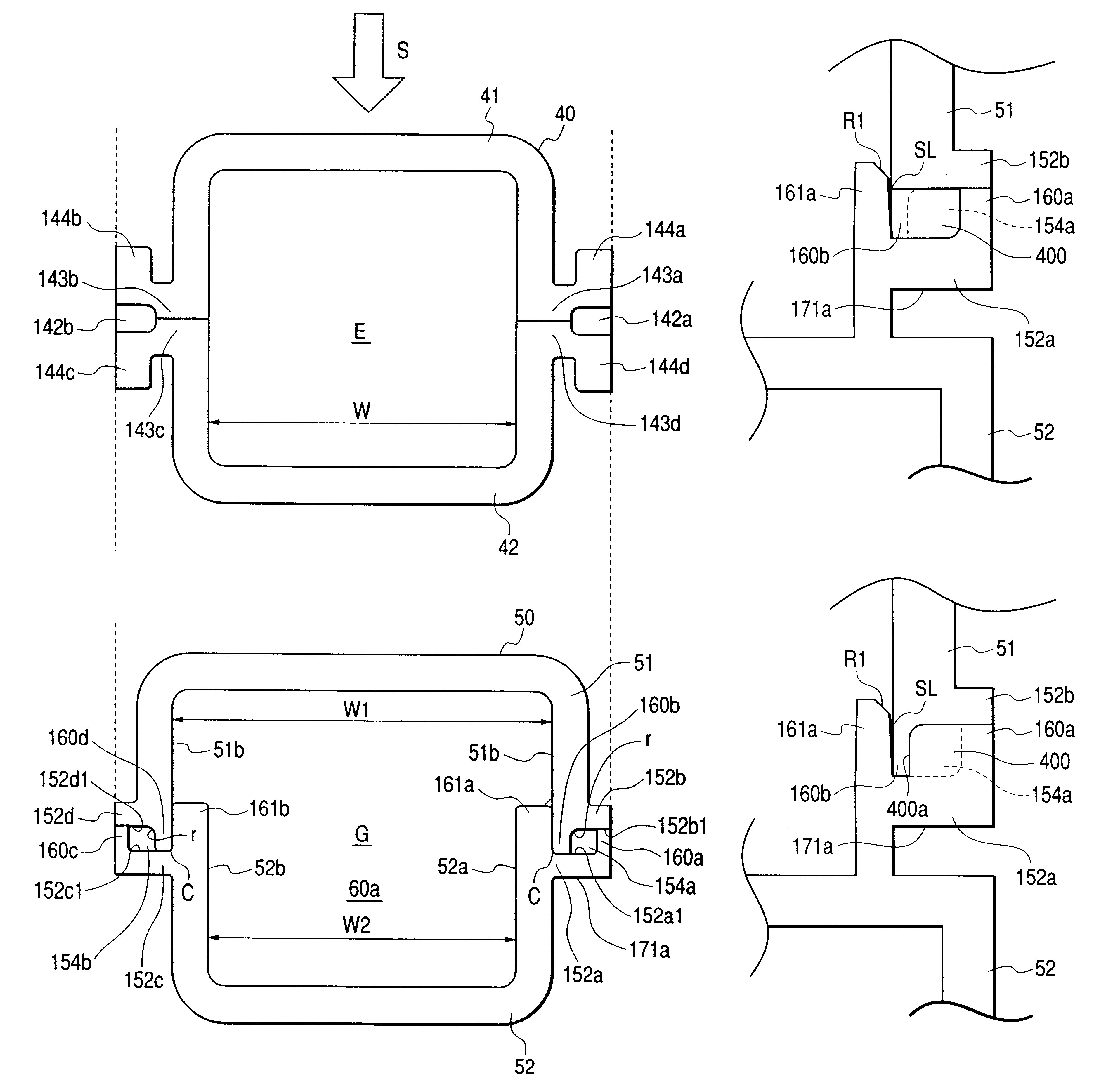
As shown in FIG. 5, although the relational positions of the respective ribs 160a, 160b and 161a are the same as those of Embodiment 1, the corner of the base side of the supporting rib 161a of the container part 52 on the lower side is not rounded. Corner chamfering R1 and an inclined plane SL are formed on the supporting rib 161a in order that the rib 160b of the container part 51 on the upper side can easily enter into the side face of the supporting rib 161a when the container parts 51 and 52 are assembled such that the parts 51 and 52 are adjacently arranged or abut against each other. Thereby, the side face on the end side of the rib 160b of the container part 51 adheres to the side face on the base side of the supporting rib 161a along the line of the side face of the rib 161a owing to the pressure of the resin flowing into the gap 154a. Consequently, the supporting ribs and the ribs of the container part 51 adhere to each other over the entire circumference of the joining po...

embodiment 7

(Embodiment 7)

According to Embodiment 6, the resin flowing in the channel 200 flows like an arrow 71b shown in FIG. 6 at the gap 154a and collides with the flange portion 152a of the container part 52. Thereby, a force P acts on the flange portion 152a owing to the variation of the kinetic momentum of the molten resin. Because the flow velocity of the resin flowing in channel 200 is large and the mass of the resin is also large, the force P becomes large.

Accordingly, in the present embodiment, as shown in FIG. 9, an undersurface 171a of the flange 152a of the container part 52 on the lower side is supported by a supporting surface 202b formed on the die 200b for the support of the container part 52.

As described above, because the supporting surface 202b of the die 200b is formed such that the supporting surface 202b crosses the extension line of the center axis x passing through the gate of the die 200a and the channel 200, the pressure imposed on the flange portion 152a by the jet ...

embodiment 8

prevents the leakage of resin to the outside at a portion where the resin injection channel 200 is connected with a gate in the case where such a channel is formed as shown in Embodiment 7. In Embodiment 8, the tip portion of a die at which a gate, in the terminology of molding techniques, which is an inlet of a molten resin material for joining, is formed, accords with the outside surface of the inlet of the resin channel of a container part forming the resin channel or is recessed in the resin channel from the outside surface.

As shown in FIG. 8, the respective center axes x of the gate 201 formed in the die 200a and the resin injection channel 200 of the container part 51 on the upper side align with each other. Suppose that the diameter of the inflow opening 200d of the channel 200 is "g", a truncated one portion 303 having the center of the center axis x projects downward from the upper surface 200a1 of the die 200a. The gate 201 is formed in the die 200a such that an inlet 201a...


PUM

PropertyMeasurementUnit
inner diameteraaaaaaaaaa

Abstract

A synthetic resin part connecting member connects at least two injection molded pieces that can be used as frames for a process cartridge detachably mountable on an image forming apparatus. The molded pieces are set in dies different from the dies used for forming the molded pieces, and a molten resin is injected into a gap formed between opposed surfaces of the molded pieces. An injection channel for the molten resin up to the gap is formed in one of the molded pieces. A rib for stopping resin is provided in the injection channel to stop the flow of the molten resin injected into the injection channel.

Description

1. Field of the InventionThe present invention relates to the configurations of an electrophotographic image forming apparatus adopting an electrophotographic image forming process such as a laser printer and an electrophotographic copying machine, and further relates to a process cartridge and the configuration of a part connecting member that is made from a synthetic resin and is for the use of the electrophotographic image forming apparatus and the process cartridge.Hereupon, the electrophotographic image forming apparatus is a device for forming an image on a recording medium by adopting an electrophotographic image forming process. Examples of the electrophotographic image forming apparatus include, for example, an electrophotographic copying machine, an electrophotographic printer (such as a laser printer, an LED printer and the like), a facsimile machine, a word processor and the like.Incidentally, the process cartridge is a device that is made by the integration of charging ...

Claims


Application Information

Patent Timeline
Patent Type & Authority Patents(United States)
IPC IPC(8): B29C45/00B29C65/40B29C65/42G03G21/18B29C33/12B29C45/14G03G15/00B29C65/70
CPCB29C45/0062B29C65/42B29C66/124B29C66/1312B29C66/54G03G21/181B29C66/543B29C66/71B29C66/5432G03G2221/1669G03G2221/1876B29C65/425B29C65/00B29C66/8322B29K2025/08B29K2025/06G03G15/00
Inventor SUZUKI, AKIRAABE, KENSHIROTSUDA, TADAYUKIHIRATSUKA, KOUICHI
Owner CANON KK
Why Eureka
Try Eureka