Sound field measuring apparatus and method

a technology of sound field and measuring apparatus, applied in the direction of vibration measurement in solids, fluid pressure measurement, specific gravity measurement, etc., can solve the problems of inability to accurately calculate the low-frequency region cannot be correctly determined, and the difficulty in correctly calculating the rising time of the speaker

Inactive Publication Date: 2003-12-02
ONKYO TECH KK
View PDF9 Cites 28 Cited by
  • Summary
  • Abstract
  • Description
  • Claims
  • Application Information

AI Technical Summary

Problems solved by technology

In the above-mentioned measuring method, however, it is difficult to correctly calculate the rising time of the speaker which indicates a response concentrated into a low-frequen

Method used


Image

  • Sound field measuring apparatus and method
  • Sound field measuring apparatus and method
  • Sound field measuring apparatus and method

Examples


Embodiment Construction

Hereinafter, an embodiment of the sound field measuring apparatus of the invention will be described with reference to FIGS. 1 to 5.

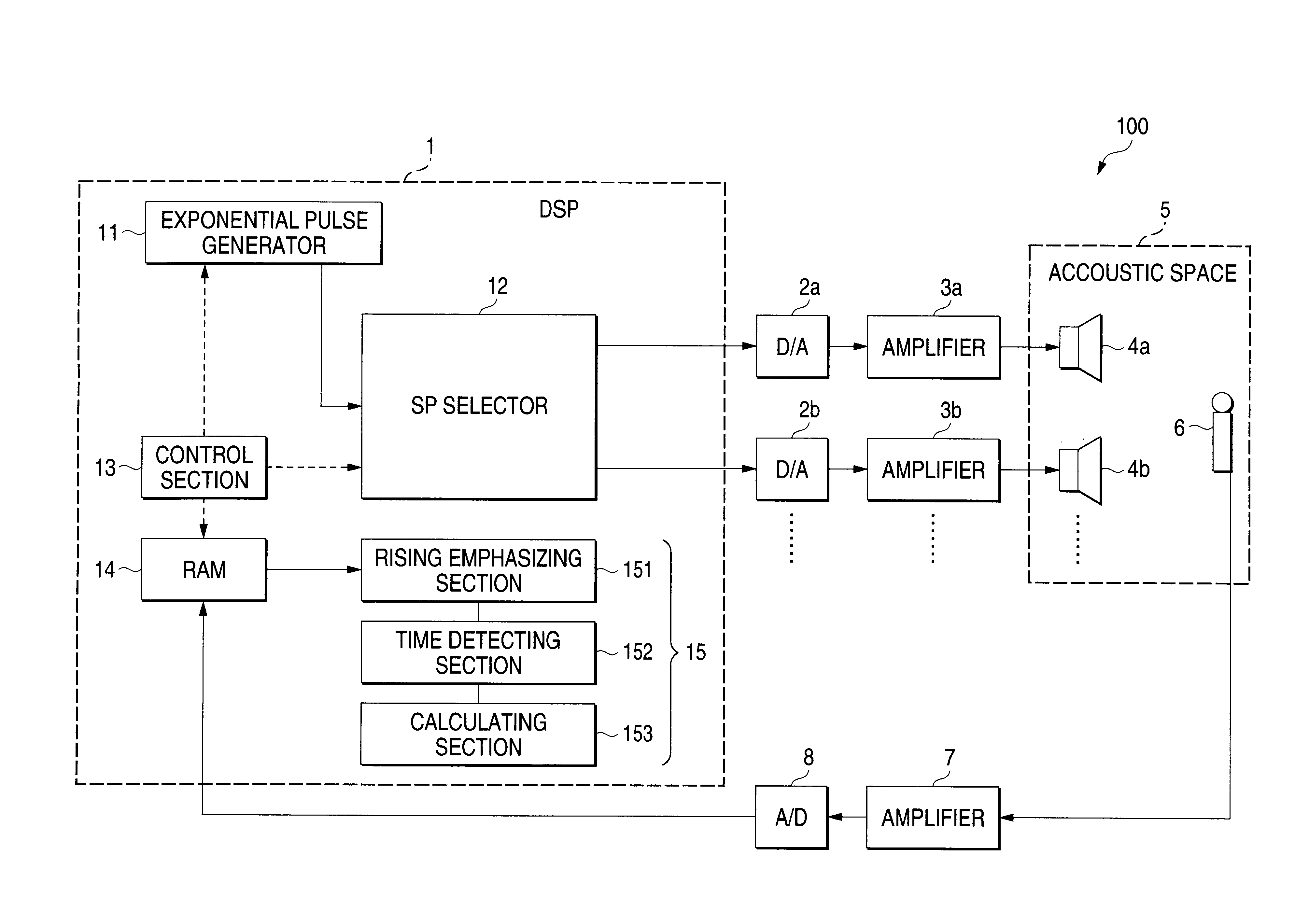
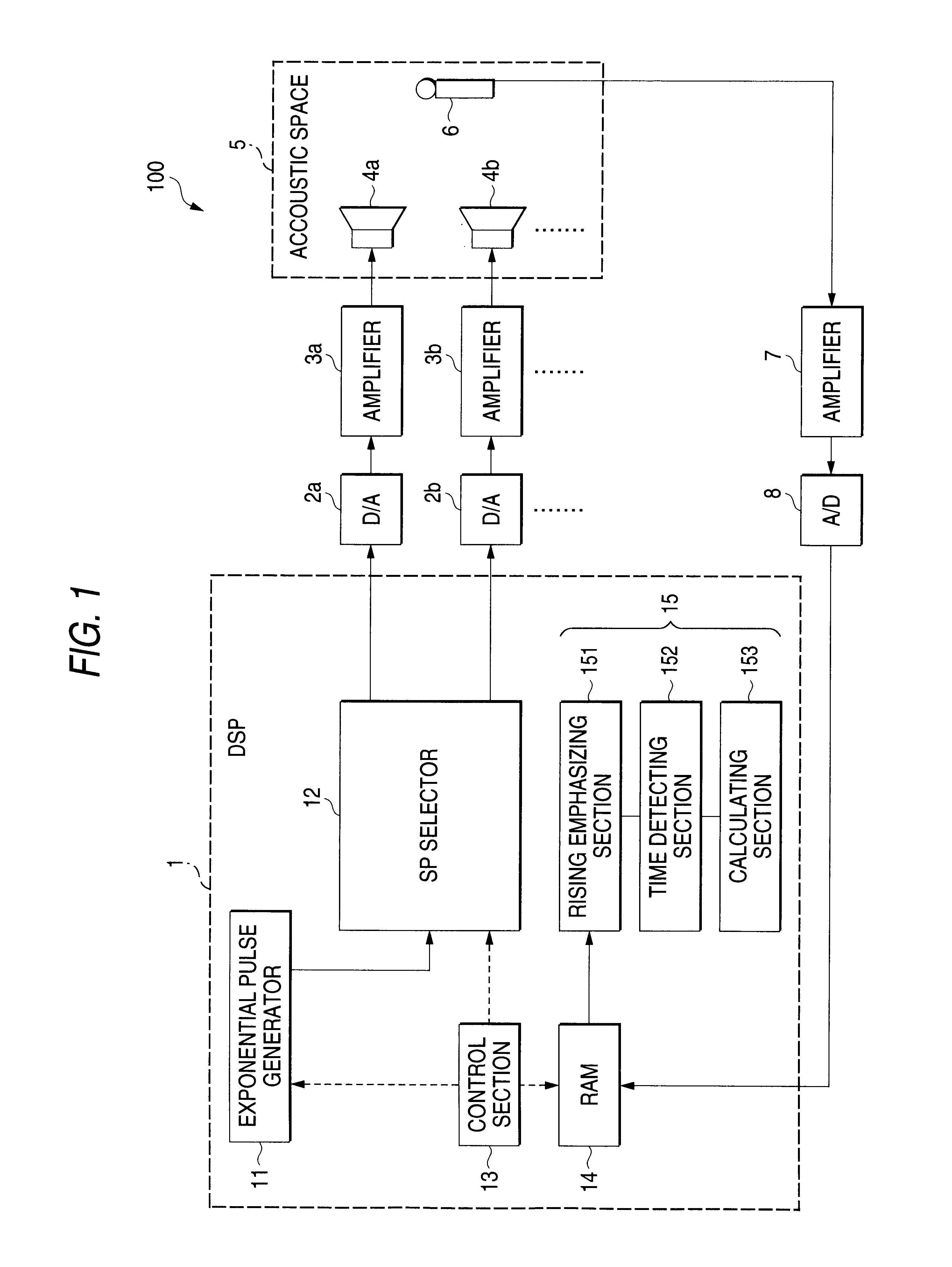
FIG. 1 is a diagram showing the configuration of a measurement system including the sound field measuring apparatus of the embodiment.

The measurement system 100 comprises: a DSP (Digital Signal Processor) 1; D / A converters 2a, 2b, . . . which receive a signal from the DSP 1; amplifiers 3a, 3b, . . . which receive signals output from the D / A converters 2a, 2b, . . . ; speakers 4a, 4b, . . . into which signals output from the amplifiers 3a, 3b, . . . are input; a microphone 6 which is disposed at a predetermined position (listening position) in an acoustic space 5 where the speakers 4a, 4b, . . . are placed; an amplifier 7 which amplifies a signal output from the microphone 6; and an A / D converter 8 which receives a signal output from the amplifier 7.

The DSP 1 comprises: an exponential pulse generator 11; a speaker selector 12; a RAM 14 for storing a rece...


PUM


Abstract

A sound field measuring apparatus has: an exponential pulse generator 11 which outputs a pulse signal to speakers 4a, 4b, . . . ; a microphone 6 which is disposed in an acoustic space 5 where the speakers 4a, 4b, . . . are disposed, and which detects a pulse signal output from each of the speakers 4a, 4b, . . . ; and a calculation section 15 which detects a time when the signal detected by the microphone 6 exceeds a predetermined threshold. The calculation section 15 calculates a time period from a time when the pulse signal is generated by the exponential pulse generator 11 to the time when the signal exceeds the predetermined threshold.

Description

1. Field of the InventionThe present invention relates to a sound field measuring apparatus and a sound field measuring method which are useful for, in an audio system having a plurality of speakers, correcting output signals for the speakers.2. Description of the Related ArtIn a conventional audio system having a plurality of speakers, it is preferable that a reproduced sound image is localized at a predetermined position and the sound field is correctly reproduced. Therefore, it is required to correctly know the time of arrival from each of the speakers to the listener. Conventionally, an impulse signal is used as means for measuring the time of arrival.The time of arrival is measured by using an impulse signal in the following manner. An impulse signal is output from a speaker. The signal is detected by a microphone disposed at a predetermined position (listening position), and an impulse response between the speaker and the microphone (listener) is calculated. In this specificat...

Claims


Application Information

Patent Timeline
IPC IPC(8): H04R29/00G01H17/00G10K15/00H04R3/12H04S1/00H04S7/00
CPCH04S7/30H04S1/002
Inventor OHTA, YOSHIKI
Owner ONKYO TECH KK
Why Eureka
Try Eureka