
Apparatus and method for aerodynamic wing

a technology of aerodynamic wings and apparatus, applied in the direction of aircraft navigation control, marine propulsion, vessel construction, etc., can solve the problems of lateral overturning moment, stability limit eventually reached, and fundamental imbalance, so as to increase the distance between the kite and the boat, the effect of easy retrieval

Inactive Publication Date: 2005-06-16
CULP DAVID A
View PDF21 Cites 29 Cited by
  • Summary
  • Abstract
  • Description
  • Claims
  • Application Information

AI Technical Summary

Benefits of technology

[0053] The apparatus of the present invention may be added to an existing vessel irrespective of whether it has a mast and sails installed. If present, the kite may be flown outside all existing rigging, or from said rigging, or in lieu of such rigging, which may then be safely removed, alleviating weight, cost and complexity associated with it. If retrofitted to existing vessels or vehicles, such a kite may profitably augment or replace existing sails, as for instance to replace a racing or cruising spinnaker with a larger kite or a same-sized kite capable of operating in significantly higher wind speeds than the replaced sail. Minimal or no alterations to the boat's existing rig need take place and the kite may or may not use the yacht's existing sail handling gear, and some or no other sail handling equipment as desired.
[0054] The kite of the present invention flies freely without rigid support of any kind other than pure tension in the flying lines and in flight inflation due to air flowing past the kite, and it may be efficiently controlled in three axes by crewmen aboard a boat or other surface vehicle via altering the relative length of the lines. In flight the shape of the kite portion of the present invention is supported solely by aerodynamic forces, said shape being designed to optimally support the structure to interact with a maximum wind cross section, to create an airfoil profile which is optimized for extracting maximum energy from moving wind, to fly in a stable and controllable manner, and to facilitate effective control by the crewmen.
[0057] Alternatively the kite may be launched “from hand” at the deck or ground level without mast or other support. In this case it is typically launched by one or two crewmen who spread the kite on the deck or ground, then present the kite's leading edge to the wind. As the kite fills with air, the line tenders tension the flying lines to retain control as the kite flies up and away. As above, the line tenders then controllably extend the flying lines both to control the kite and to increase the distance between the kite and boat.
[0058] The preferred embodiment of the invention has another emergency method for eliminating all power and retrieving the kite. If all flying lines and launch / retrieval lines are suddenly made slack, with the exception of the tail line(s), the kite will immediately fold upon itself and will lose all power from the wind. In such case it presents a minimal area to either wind or water and is relatively very easy to retrieve via the tail line(s). This method is suitable for recovery of the kite in very high winds, or when it has entered the water, or when there is a gear failure or other emergency aboard the boat. So long as the lines can be made slack, through lengthening, releasing or even cutting them away, the kite may be rendered powerless and conveniently retrieved.

Problems solved by technology

While using kites, parachutes and other kite-like devices to draw sailing vehicles is not a new enterprise, to date most existing sailcraft utilize a fundamentally imbalanced force couple when connecting their wind-effected elements to their water-effected elements.
This imbalance causes a lateral overturning moment, which most sailing craft counter either by the addition of ballast below the vessel's center of buoyancy, or by offsetting significant structure athwartships, or both.
In addition to cost, weight and drag increases associated with either solution, a stability limit is eventually reached whereby no more sail area, or no greater wind speed may be utilized.
Alternatively, such a vessel can be designed with far less inherent stability, or utilizing significantly decreased weight, cost, and / or complexity.
Friction and turbulence with the water's surface slows surface winds appreciably for some distance above the water's surface.
Some are difficult to deploy or fly in close proximity to boat hulls.
Others are difficult or dangerous to assemble, launch or recover in high winds.
Others have low wind thresholds, or stall speeds, which are too high to make them useful in light winds.
Still others are expensive to produce or difficult or expensive to maintain and repair.
In the case of kites with rigid or semi-rigid frames, multiple bridles or else triangular or quadrilateral shaped pieces of material attached at one edge and standing out from the kite's surface called keels or flares make it possible for these frame elements to be proportionally smaller and lighter, however both the weight of the frame and the air drag of multiple bridle lines or keels are detrimental to cost, aerodynamic efficiency and manufacturing simplicity.
In the case of simple soft flat or hemispherical-shaped kites the major drawback for sailing use revolves around two issues; multiple bridle lines and aerodynamic efficiency.
Many-bridled kites are difficult to launch from the crowded and complex confines of typical boat decks.
Playsail-type kites (for example, see: http: / / www.nvke.org / Play Sail Workshop.htm) need a large separation of their flying anchors and suffer leading edge collapse upon acceleration, thus are not presently used in sailing applications.
In the case of conventional Jalbert, parafoil or parapent style foil kites that use ram air inflation as their structural element, the pressure differential available is so small as to allow no possibility of sufficient span wise beam strength without support from multiple bridles spaced at intervals both chord wise and span wise.
Bridle lines do however, in themselves, add undesirable drag and often tangle during launching from deck or during flying in such a way as to prevent satisfactory operation of the kite.
These kites are typically heavier than non-framed kites and are not amenable to scaling to large sizes, due to physical scaling factors increasing their specific weight (weight per unit area) unfavorably.
This kite is still heavier than frameless kites and, as it partially relies on its rigid framework, still suffers from scaling factors at large sizes.
In addition, both these and framed kites are typically characterized by sharp leading edges, which limit the kite's ability to respond efficiently to varying or extreme angles of attack.
This type of kite is light in weight as it is both frameless and is built of a single layer of structural material, but it suffers drag penalties associated with its multiple bridle lines (typically 30-50 lines) and its generally non-smooth surface shape.
In addition, multiple-bridled kites suffer from tangling issues during launch and recovery operations.
Also, as many of the bridle lines are taken to the kite's interior surface, strong tearing and peeling loads are created throughout the structure, which make local reinforcing necessary and scaling problematic.
These kites are typically heavier and more expensive than single-skinned frameless kites, yet lighter than rigid or semi-rigid framed kites.
They suffer from minimal available inflation pressure, necessitating either thicker than optimal airfoil profiles, the need for multiple bridle lines with their attendant tangling and drag problems, or both.
This kite solves the multiple bridle issue, but substitutes unwanted added weight of a substantial cantilevered solid spar at its leading edge, and also suffers from scaling issues.
This kite thus suffers similar scaling issues to framed kites previously cited.
These kites either have substantially a single layer skin (Barish) or minimal bridle lines (Lynn), but each suffers from one or more of the drawbacks of other kites cited above, i.e., high weight, peel or tearing forces, manufacturing complexity, line tangling or scaling limitations.

Method used


Image

  • Apparatus and method for aerodynamic wing
  • Apparatus and method for aerodynamic wing
  • Apparatus and method for aerodynamic wing

Examples


Embodiment Construction

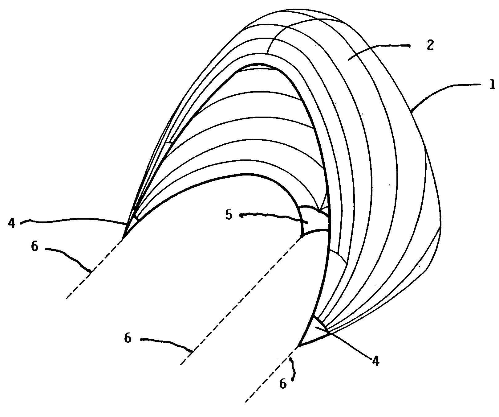
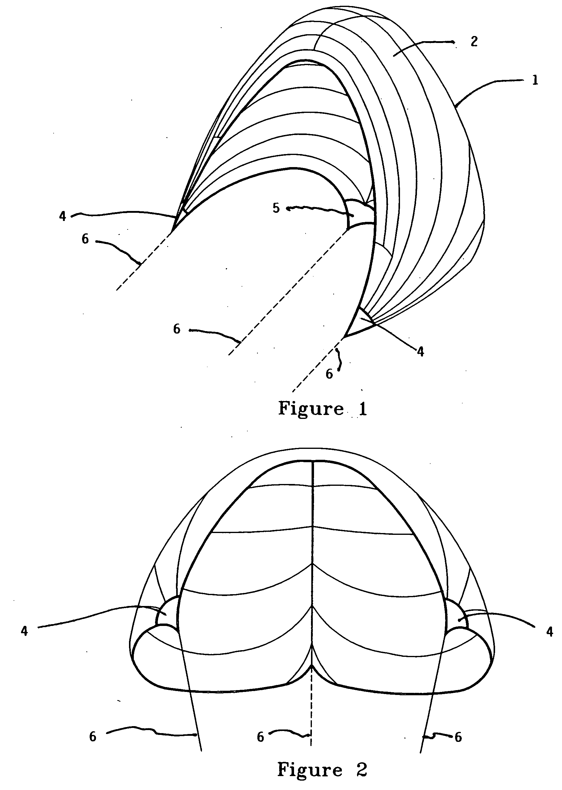
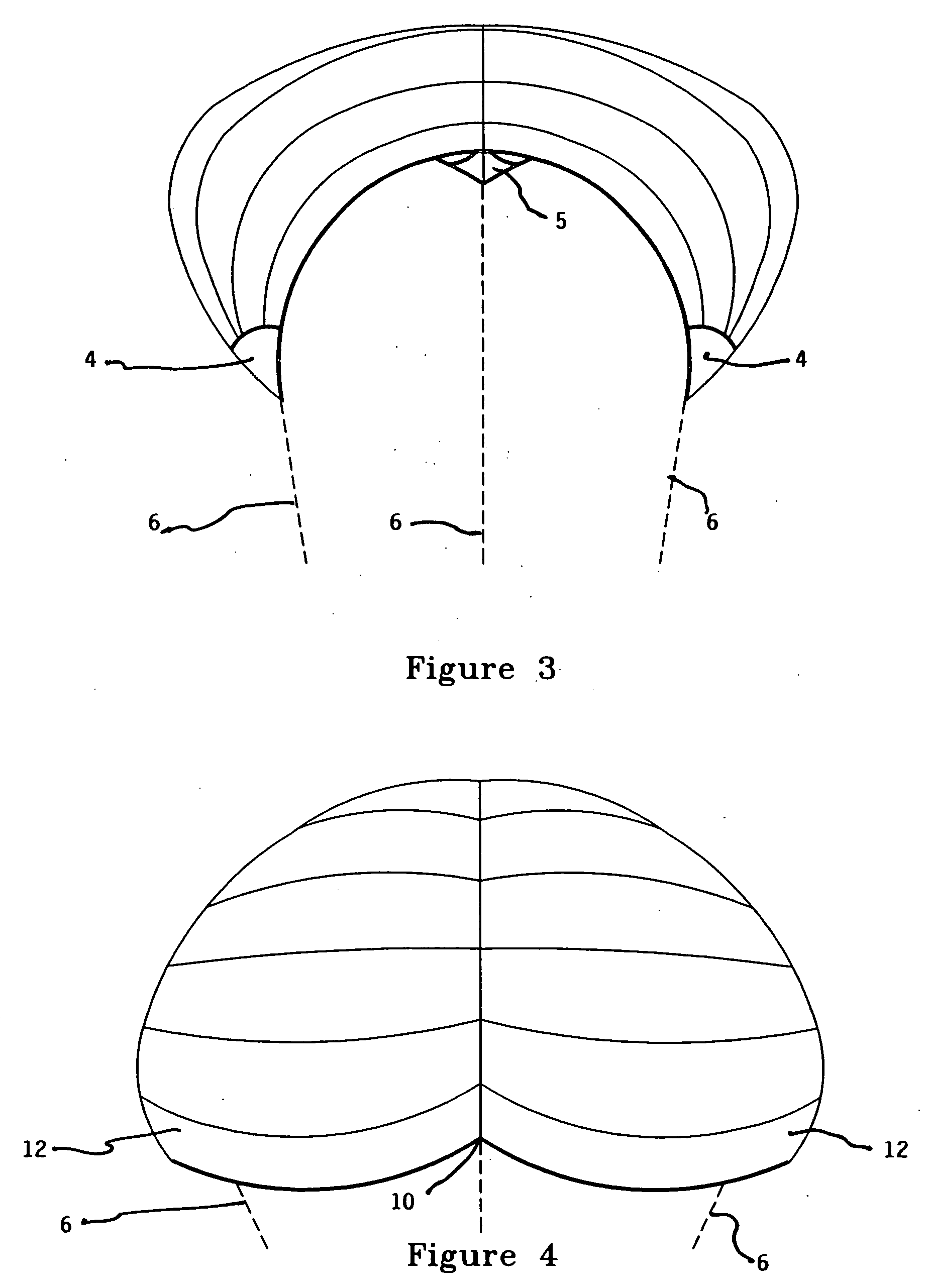
[0072] The preferred embodiment of the present invention differs from any existing or past sail or kite in a number of respects. First it contains a unique combination of several attributes: [0073] a) It is comprised of a three-dimensional shape (FIGS. 1-6) that is inherently stable and powerful in flight, and capable of positive control via altering flying line lengths 6. This shape is capable of supporting factors b), c), and d) below. [0074] b) It is made of a single flexible skin 1 of uniform or variable density and contains no surface discontinuities, “keels,”“flares” or similar. It is relatively lighter and stronger than similar kites with flares, as these typically impose tearing or peeling stresses on kite structures for which the structures must be designed. It contains no enclosed cells, double surfaces or interior structure of any kind. As such it is simple and inexpensive to manufacture, to maintain and to repair. It is relatively lighter in weight than other kites. [007...


PUM


Abstract

Aerodynamic wing to propel a broad range of transport means, principally sail craft. The wing provides a single layer kite structure capable of flying without surface discontinuity, bridles, or rigid or semi-rigid structure. All stresses within the wing are converted into pure tension and transferred through the wing surface outward to attachment lines. The wing shape defines a large diameter self-supporting rolled over leading edge of an airfoil and the wing profile approaching the trailing edge exhibits increasing convexity. The wing is useful to propel, or supplement propulsion to, transportation means.

Description

CROSS-REFERENCES TO RELATED APPLICATIONS [0001] None. STATEMENT REGARDING FEDERALLY SPONSORED RESEARCH OR DEVELOPMENT [0002] None. REFERENCE TO A MICRO-FICHE APPENDIX [0003] None. BACKGROUND OF THE INVENTION [0004] 1. Field of the Invention [0005] The present invention relates to aerodynamic devices or wings typically used to propel boats, vehicles or persons across water, land or ice or snow, to propel airborne craft above ground or in space, or to propel nano-technological devices. More specifically this invention relates to an improved aerodynamic device and method of using the same designed to replace specialized downwind and cross wind sails on sailing boats sometimes referred to as spinnakers. The improved aerodynamic device and method of the present invention is applicable to mono-hulled, and multi-hulled boats in a variety of tonnages. [0006] 2. Description of the Related Art [0007] A search of the prior art located the following United States patents which are believed to b...

Claims


Application Information

Patent Timeline
Patent Type & Authority Applications(United States)
IPC IPC(8): B63H9/06B64C31/06
CPCB63H9/0685Y10S244/902B64C31/06B63H9/071B63H9/072Y02T70/5236
Inventor CULP, DAVID A.
Owner CULP DAVID A
Learn More