Fast charging power bank

a power bank and fast charging technology, applied in the direction of dc circuit to reduce harmonics/ripples, safety/protection circuits, transportation and packaging, etc., can solve the problems of excessive charging time of the power bank, -usb port often encounters current limitations, and often consumes battery power, etc., to increase the charging current and reduce the charging time.

Inactive Publication Date: 2016-08-04
DIGIPOWER MFG
View PDF1 Cites 30 Cited by
  • Summary
  • Abstract
  • Description
  • Claims
  • Application Information

AI Technical Summary

Benefits of technology

[0007]The invention is directed to a fast charging power bank capable of increasing a charging current in the power bank to reduce charging time.
[0008]In an embodiment of the invention, a fast charging power bank that includes at least one battery, a plurality of input ports, and a charging control unit is provided. The charging control unit includes a plurality of input boosters and a charging control circuit. The input ports are configured to respectively receive a plurality of input powers as a plurality of charging powers from a plurality of external power supplies. The input boosters are connected to each other in parallel. Each of the input boosters is correspondingly connected to an independent one of the input ports to receive one of the charging powers. An output terminal of each of the input boosters is connected to each other and connected to a boost bus. The input boosters respectively step up voltages of the charging powers to output a boosting voltage and control a current of each of the charging powers, so as to provide more significant energy and charge the at least one battery. Each of the input boosters controls the current of each of the charging powers to balance the input powers and prevent overload of the input powers. The charging control circuit is connected between the boost bus and the at least one battery. The charging control circuit is configured to control the boost bus and convert the boosting voltage into a charging current. The charging control unit also outputs the charging current to the at least one battery, so as to charge the at least one battery.
[0018]In light of the foregoing, the fast charging power bank is able to receive the input powers from the external power supplies through the input ports, so as to add up the powers. Hence, large charging current can be provided to the at least one battery in the power bank. Thereby, the charging action performed on the at least one battery can be accelerated, and the charging time of the at least one battery can be reduced. Moreover, each input booster is connected to one independent input port corresponding to the input booster to receive the charging power; accordingly, the processing circuit is able to control the current of each input booster, so as to control the voltage at the boost bus and adjust the charging current of the at least one battery.

Problems solved by technology

Said functions of the mobile apparatuses often consume power of batteries in the mobile apparatuses at a fast pace.
Subject to the specifications of the micro-USB port, the micro-USB port often encounters limitations on currents, which also poses an impact on the charging current of the power bank.
If the power bank with the large capacity still performs the charging action by applying the charging current provided by one single micro-USB port, the charging time of the power bank may be excessively long, which may cause inconvenience to users.

Method used


Image

  • Fast charging power bank
  • Fast charging power bank
  • Fast charging power bank

Examples


Embodiment Construction

[0023]Descriptions of the invention are given with reference to the exemplary embodiments illustrated with accompanied drawings, wherein same or similar parts are denoted with same reference numerals. In addition, whenever possible, identical or similar reference numbers stand for identical or similar elements in the figures and the embodiments.

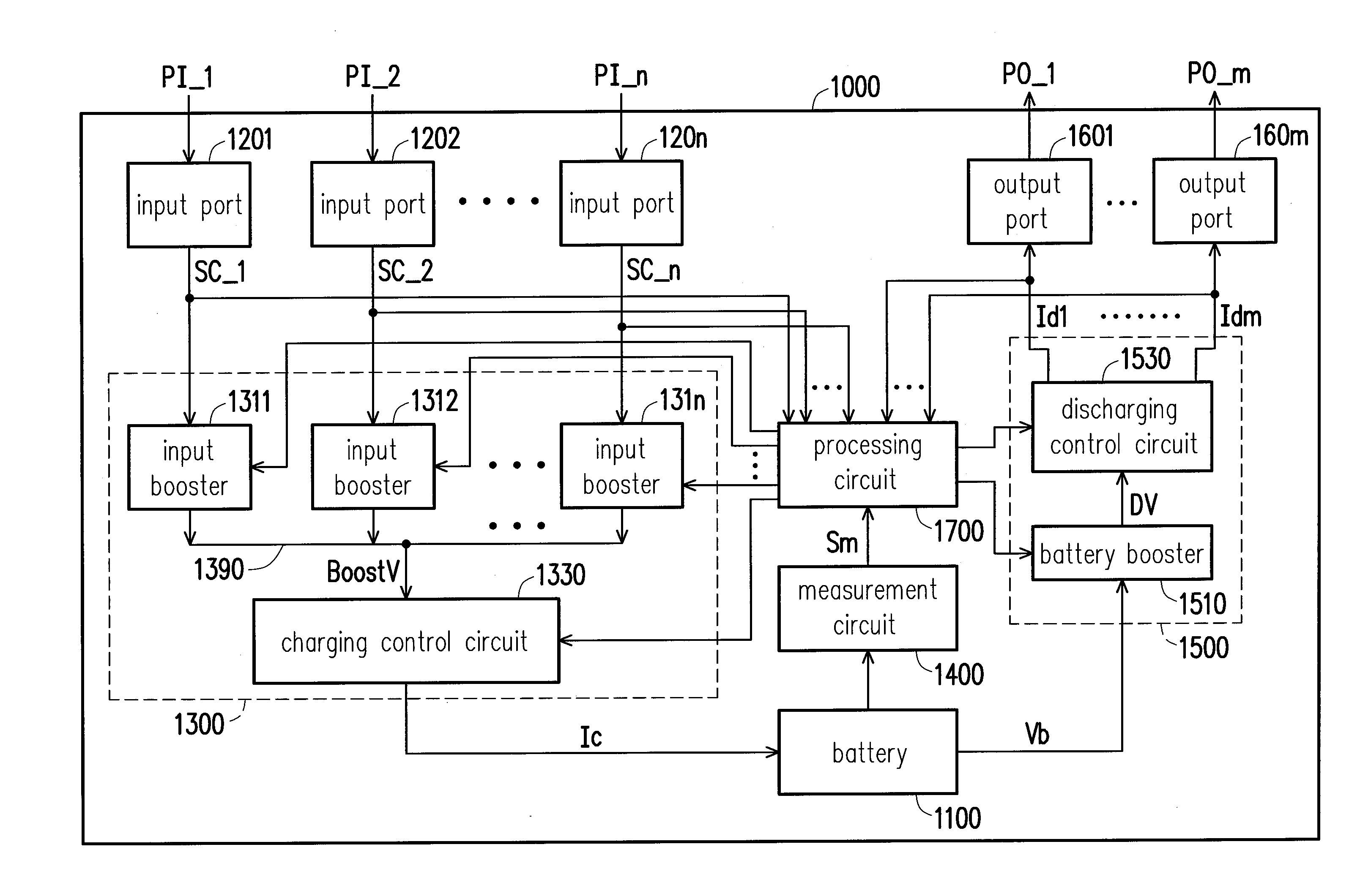
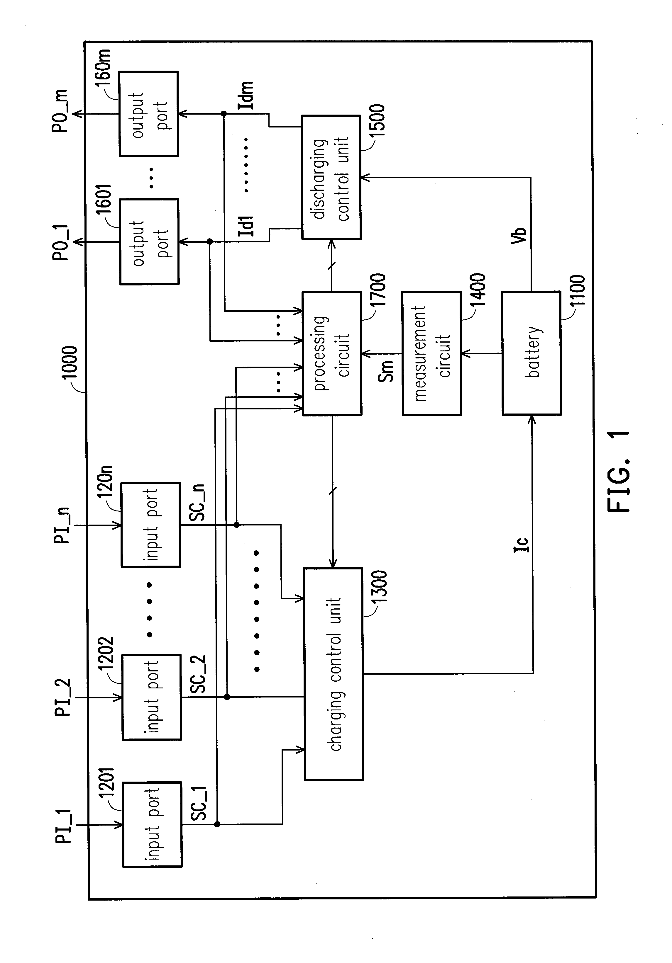
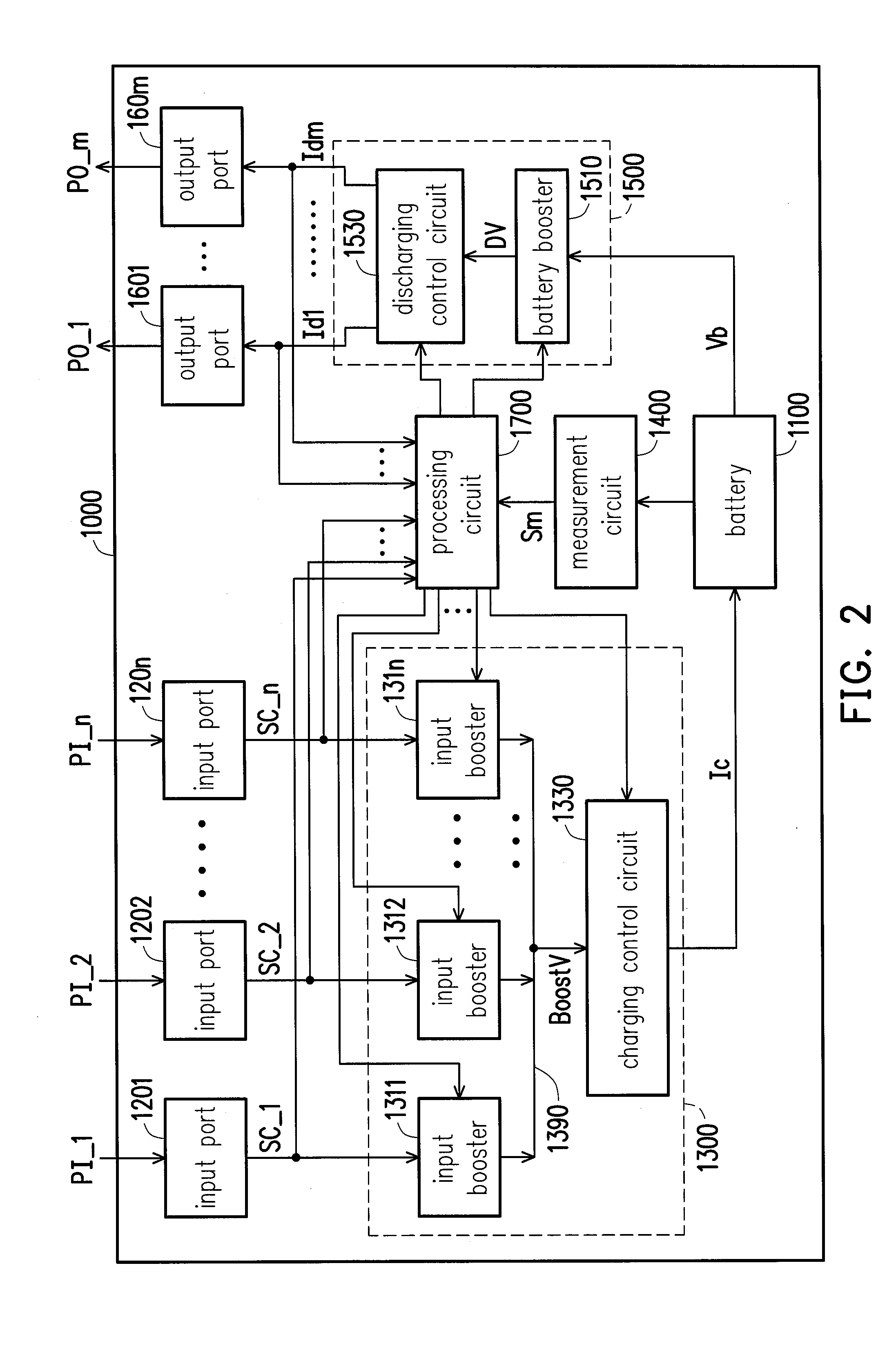
[0024]FIG. 1 is a schematic block diagram illustrating a fast charging power bank 1000 according to an embodiment of the invention. The fast charging power bank 1000 includes a battery 1100, a plurality of input ports 1201-120n, a charging control unit 1300, a measurement circuit 1400, a discharging control unit 1500, a plurality of output ports 1601-160m, and a processing circuit 1700.

[0025]The battery 1100 may stand for one single battery (or a battery device), a battery set, or a module that includes one or more batteries (or battery devices). Besides, the battery 1100 may be a rechargeable battery, such as a nickel-zinc battery, a nickel-...


PUM


Abstract

A fast charging power bank is provided. The fast charging power bank includes a battery, input ports, and a charging control unit. The charging control unit includes boosters and a charging control circuit. Each of the input ports is configured to receive input power as charging power. The boosters are connected to each other in parallel and control currents of the input powers respectively to obtain fast charging power and supply the fast charging power to the battery. Each of the boosters is correspondingly connected to an independent one of the input ports to receive the charging power. The boosters step up voltages of the charging powers respectively and output a boosting voltage to a boost bus. The charging control circuit is connected between the boost bus and the battery and configured to convert the boosting voltage into a charging current for charging the battery.

Description

CROSS-REFERENCE TO RELATED APPLICATION[0001]This application claims the priority benefit of Taiwan application serial no. 104201415, filed on Jan. 29, 2015. The entirety of the above-mentioned patent application is hereby incorporated by reference herein and made a part of this specification.BACKGROUND OF THE INVENTION[0002]1. Field of the Invention[0003]The invention relates to a power supply; more particularly, the invention relates to a fast charging power bank.[0004]2. Description of Related Art[0005]The rapid development of mobile apparatuses allows normal mobile apparatuses to be equipped with high-resolution screens, to take pictures, to display video clips, to access to a wireless internet connection, and so forth. Said functions of the mobile apparatuses often consume power of batteries in the mobile apparatuses at a fast pace. Users of the mobile apparatuses are frequently required to prepare an additional power bank for charging the mobile apparatus and avoiding depletion...

Claims


Application Information

Patent Timeline
Patent Type & Authority Applications(United States)
IPC IPC(8): H02J7/00
CPCH02J7/0013H02J7/007H02J7/0052H02J1/02H02J7/0068H02J7/00302H02J2207/40H02J7/00306H02J7/00
Inventor HUANG, MIN-HUANG
Owner DIGIPOWER MFG
Why Eureka
Try Eureka