Heat dissipation device by liquid cooling

a technology of heat dissipation device and liquid cooling, which is applied in the direction of electrical apparatus construction details, light and heating apparatus, laminated elements, etc., can solve the problems of slow heat transfer performance, achieve the effect of reducing the meandering of liquid flowing, increasing the surface area of heat transfer, and shortening the length of the channel

Inactive Publication Date: 2003-12-02
HSIEN CHO CHANG
View PDF7 Cites 75 Cited by
  • Summary
  • Abstract
  • Description
  • Claims
  • Application Information

AI Technical Summary

Benefits of technology

It is therefore a principal object of the invention to provide a heat dissipation device by liquid cooling that can increase the surface area of heat transfer, the area of the channel, shorten the length of the channel, and reduce the meanders of liquid flowing inside the heat dissipating device. Thereby, flowing of a substantial amount of liquid is allowed, and the resistance to liquid flowing is reduced.

Problems solved by technology

However, since the cooling liquid flows are in a channel that is flat, turbulence effect of the cooling liquid is not optimized and thus the performance of heat transfer is very slow.

Method used


Image

  • Heat dissipation device by liquid cooling
  • Heat dissipation device by liquid cooling
  • Heat dissipation device by liquid cooling

Examples


Embodiment Construction

Wherever possible in the following description, like reference numerals will refer to like elements and parts unless otherwise illustrated.

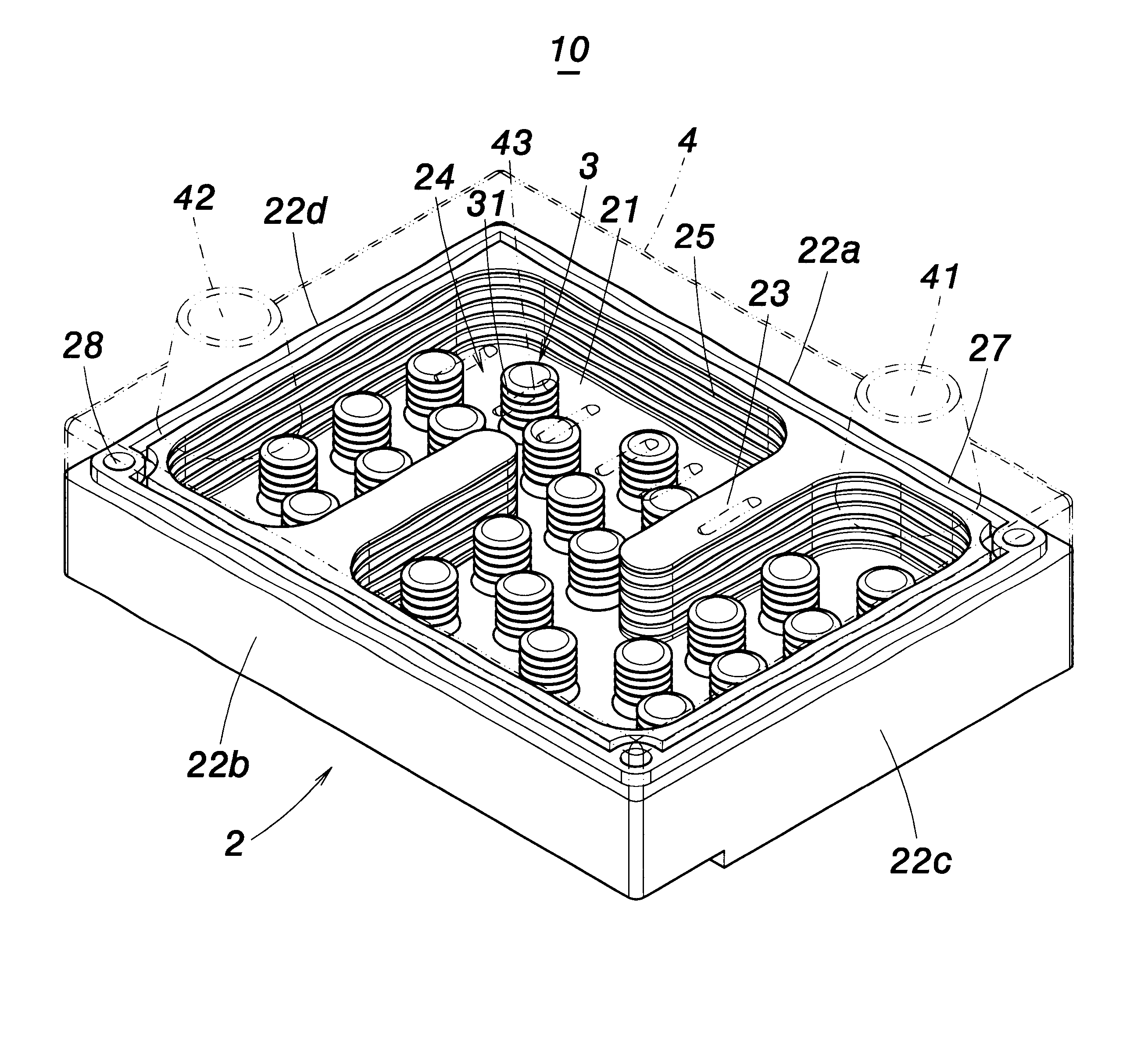
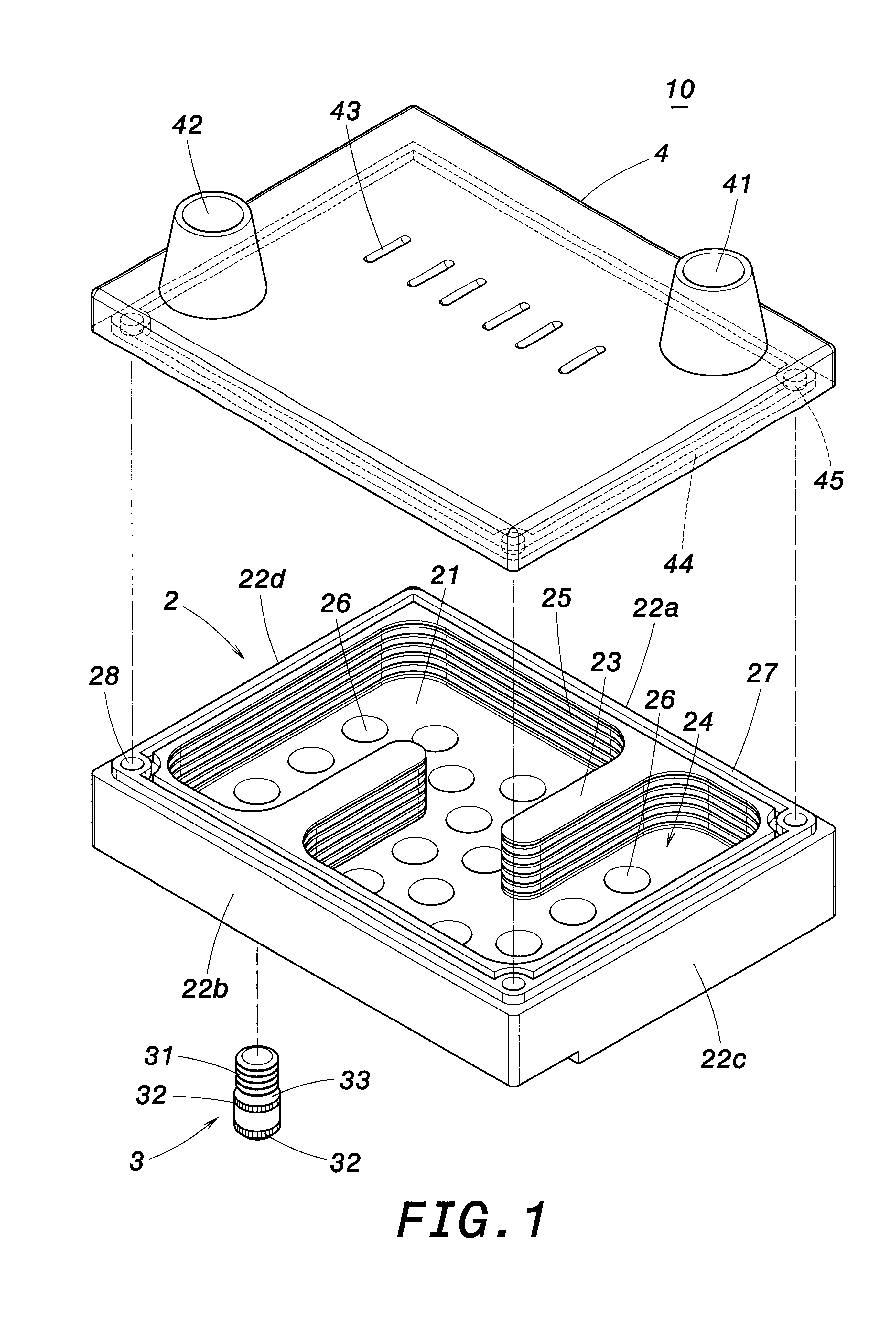
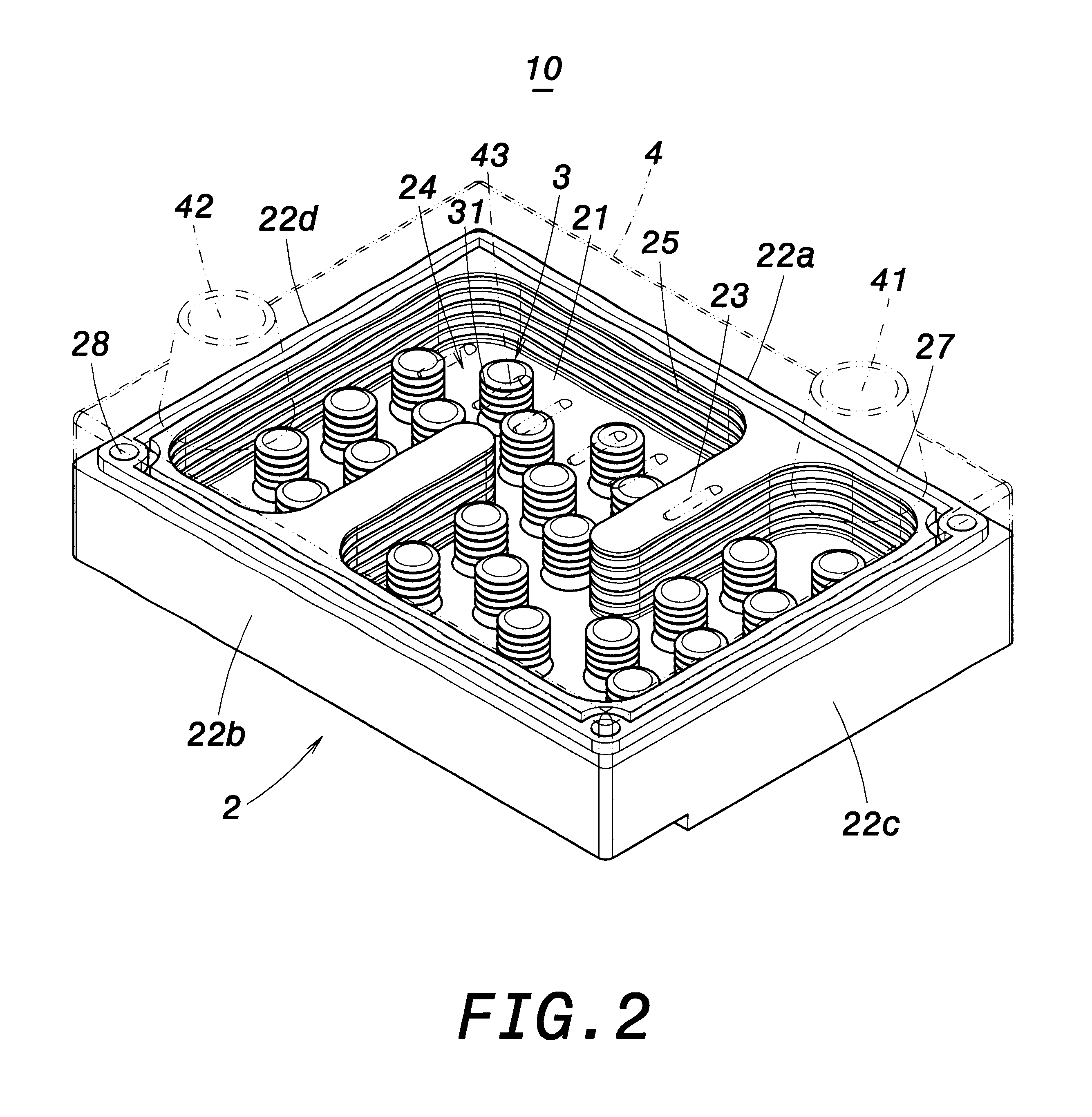
Referring to FIG. 1, the invention provides a heat dissipation device 10 by liquid cooling that is used to dissipate heat from a central processor unit 1 or chipset of a computer as shown in FIG. 6. The heat dissipation device 10 comprises a casing 2, forming a liquid container made of copper. The casing 2 includes a bottom 21 that is respectively connected to opposite sidewalls 22a, 22b and opposite sidewalls 22c, 22d in a single body. A central area of the casing 2 includes a spacing wall 23 that defines an S-shaped channel 24 inside the casing 2.

Furthermore, the sidewalls 22a, 22b, 22c, 22d respectively include striated inner surfaces where are formed toothed projections 25 by milling cutting. The bottom 21 of the casing 2, within the channel 24, is provided with a plurality of alternating through-holes 26. A protruding rib 27 runs on the top ...


PUM


Abstract

A heat dissipation device by liquid cooling includes a casing, which has a spacing wall to form a channel therein. The casing has sidewalls and the inner surfaces of the sidewalls and the surface of the spacing wall are provided with a plurality of first toothed projections. An upper cover covers the casing and includes a liquid outlet and a liquid inlet at locations respectively corresponding to two corners of the channel. A plurality of posts are alternately placed inside the channel and a surface of each post is provided with a plurality of second toothed projections. Thereby, a liquid flowing inside the channel of the casing strikes the first and second toothed projections to promote flowing turbulence and increase heat transfer surface areas for heat dissipation.

Description

1. Field of the InventionThe invention relates to a heat dissipation device by liquid cooling. More specifically, the invention relates to a heat dissipation device that is used for a CPU or IC chipset, and provides an improved heat dissipation.2. Description of the Related ArtIn accordance with the heat dissipating device known in the prior art, it comprises an approximately cuboid frame having first and second pairs of opposite sidewalls. A plurality of electric parts are mounted on the frame. A motherboard is further mounted on the frame. The motherboard has a plurality of slots in one of which a processor board is inserted, the processor board mounting a chip irradiating heat thereon. A power supply is mounted inside the frame, wherein one side of the power supply is proximate to one of the first sidewalls and the other side proximate to one of the second sidewalls. A fan is further mounted proximate to the power supply. A heat transfer assembly for dissipating the heat generate...

Claims


Application Information

Patent Timeline
Patent Type & Authority Patents(United States)
IPC IPC(8): H01L23/34H01L23/473H05K7/20
CPCH01L23/473H01L2924/0002H01L2924/00
Inventor HSIEN, CHO-CHANG
Owner HSIEN CHO CHANG
Why Eureka
Try Eureka