Impact damper

a technology of impact damper and spherical damper, which is applied in vibration dampers, mechanical equipment, transportation and packaging, etc., can solve the problems of increasing the cost of the device, increasing the pressure, and reducing the size of the first gas spa

Inactive Publication Date: 2003-12-02
ZF BOGE
View PDF14 Cites 11 Cited by
  • Summary
  • Abstract
  • Description
  • Claims
  • Application Information

AI Technical Summary

Benefits of technology

The fittings of the impact damper are configured in such a way that they can be activated within fractions of a second and can vary the impact-damper setting in such a way that the shock to be expected against the bumper can be taken in an optimum way when the motor vehicle is involved in a collision.
In the case of collisions with low shock loading, the inner tube is pushed into the outer tube, only the first gas space being reduced in size, and the gas charge being compressed. In this process, the interaction of the first liquid space with the second liquid space performs damping functions by virtue of the fact that liquid is forced from the second liquid space into the first liquid space through the restriction orifice in the partition wall. As a result, the first liquid space increases in size by virtue of the fact that the dividing piston slides in the inner tube in the direction of the bumper and reduces the size of the first gas space and thus increases the pressure there. Once inward motion is finished, the gas spring formed by the first gas space ensures that the inner tube returns to its initial position.
It is possible likewise to connect the first gas space to a regulating valve and then to the accumulator via a pneumatic feed line, making it possible to vary the gas spring for collisions involving relatively low shock loading. However, such a measure increases the cost of the device and is therefore feasible only on more valuable motor vehicles. The preloading in the first gas space is therefore chosen to allow primarily for collisions with two-wheeled vehicles or pedestrians.
The presence of the deformation element has been found to be advantageous in the case of collisions with the highest shock loads, the deformation element being pushed with a diameter corresponding to the diameter of the outer tube into the reduced-diameter end of the tube, expanding the latter and absorbing deformation work, as a result of which the frame of the motor vehicle may remain free from deformation and repair of the motor vehicle may be limited to replacement of the impact dampers and possibly of the bumper. During this process, the control valve is fully open, and the pneumatic pressure in the compensation space is raised to the maximum possible value in order to fully exploit the potential of the spring forces in the gas spaces as well.

Problems solved by technology

As a result, the first liquid space increases in size by virtue of the fact that the dividing piston slides in the inner tube in the direction of the bumper and reduces the size of the first gas space and thus increases the pressure there.
However, such a measure increases the cost of the device and is therefore feasible only on more valuable motor vehicles.
However, the damping work can be performed by the impact damper in this manner only once, since the liquid can be returned from the compensation space only under specific workshop conditions, if at all.
Moreover, the inner tube is no longer returned to the initial position because of the reduction in size of the liquid spaces.

Method used


Image

  • Impact damper
  • Impact damper

Examples


Embodiment Construction

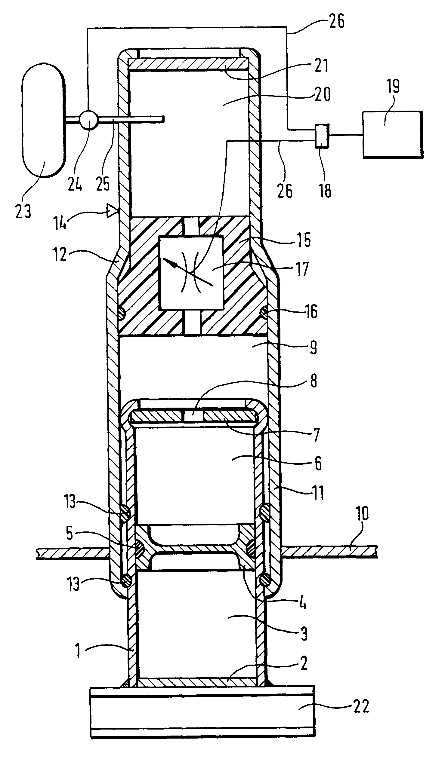
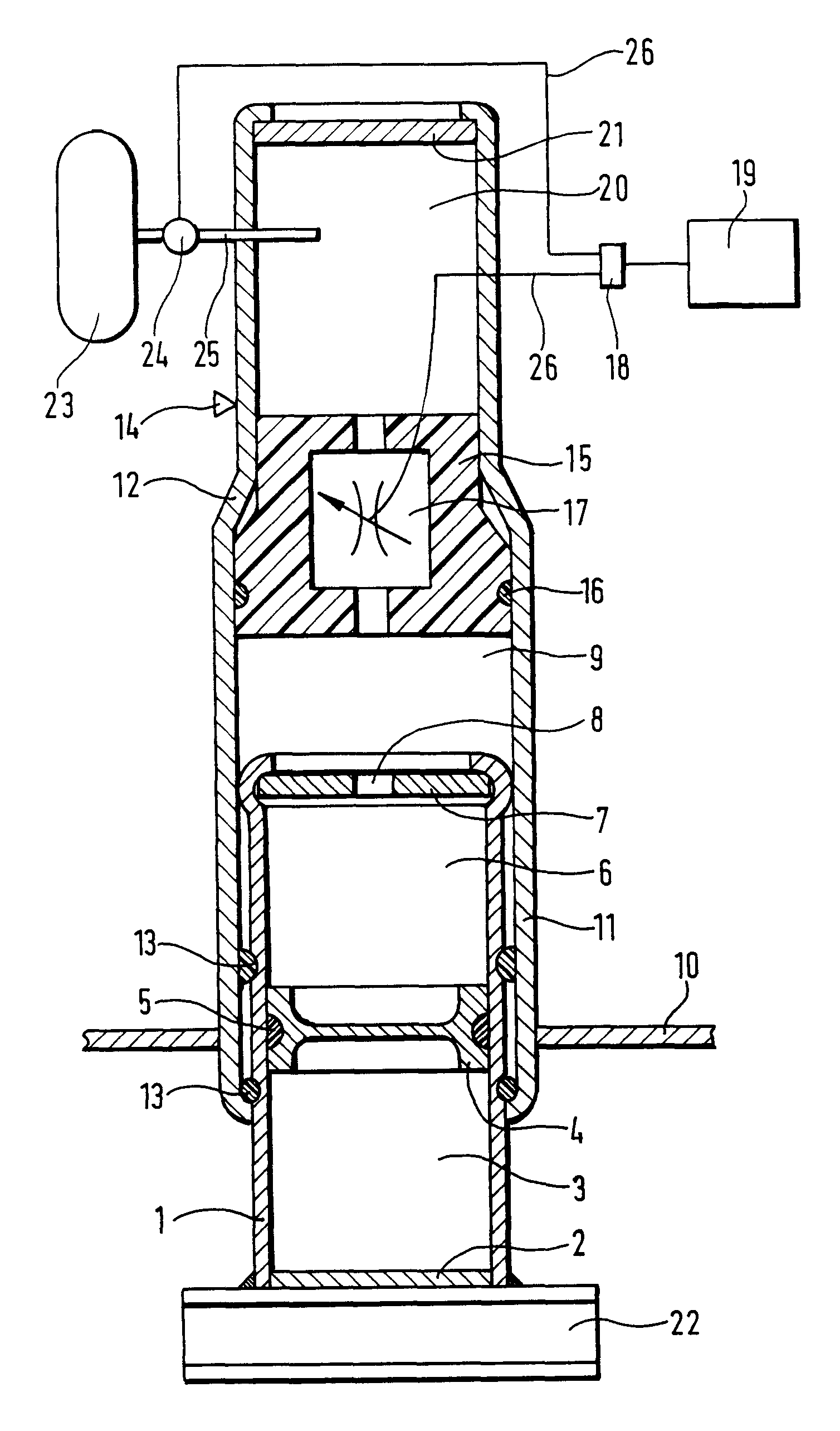
The FIGURE shows a variable-length impact damper for a chassis of a motor vehicle, an inner tube 1, closed off from the outside by a wall 2, enclosing a first gas space 3, which is provided with a gas charge under high pressure. Connected to the wall 2 and / or the inner tube 1 is a fastening element 22, which connects the impact damper to a bumper. A first liquid space 6, which is likewise situated in the inner tube, is separated from the first gas space 3 by a dividing piston 4, which is sealed off by means of a sealing ring 5 and slides on the inner wall of the inner tube 1. At the opposite end from the dividing piston 4, the first liquid space 6 is bounded by a partition wall 7, which is secured in the inner tube 1 and is provided with a restriction orifice 8 and hence establishes a hydraulic connection with a second liquid space 9, which is likewise arranged in the inner tube 1. The inner tube 1 slides on the inner wall of an outer tube 11 and is sealed off by at least one sealin...


PUM


Abstract

An impact damper as a connecting member between a bumper and a chassis of a motor vehicle for the purpose of damping the shock loading during a collision between this motor vehicle and an obstacle through hydraulic damping forces and gas-spring forces. This impact damper includes an inner tube which can be displaced telescopically inside an outer tube, thereby changing the volume of a pressurized gas space, which interact by means of a separating piston with a first liquid space, which communicates hydraulically via a restriction orifice with a second liquid space, which is bounded by a deformation element. The separating piston is arranged in a floating manner in the inner tube and thereby brings about a static equilibrium by pressure compensation in the liquid spaces and in the gas space. The outer tube furthermore has a drawn-in portion around the deformation element, which brings the outer tube to a reduced diameter, within which is arranged a compensation space that can be filled with gas formed by an end wall at the end of the outer tube. The deformation element has an adjustable control valve, which can be controlled from outside the impact damper by a detection sensor system. The compensation space furthermore communicates with an accumulator, which can likewise activate the pressure in the gas spaces in response to the detection sensor system.

Description

1. Field of the InventionThe invention relates to an impact damper as a connecting member between a bumper and a chassis of a motor vehicle for the purpose of damping the shock loading during a collision between this motor vehicle and an obstacle through hydraulic damping forces and gas-spring forces. This impact damper essentially includes an inner tube, which can be displaced telescopically inside an outer tube, thereby changing the volume of a pressurized gas space, which interact by means of a separating piston with a first liquid space, which communicates hydraulically via a restriction orifice with a second liquid space, which is bounded by a deformation element. The separating piston is arranged in a floating manner in the inner tube and thereby brings about a static equilibrium by pressure compensation in the liquid spaces and in the gas space. The outer tube furthermore has a drawn-in portion around the deformation element, which brings the outer tube to a reduced diameter,...

Claims


Application Information

Patent Timeline
Patent Type & Authority Patents(United States)
IPC IPC(8): F16F9/00F16F9/46F16F9/44F16F9/06
CPCF16F9/46F16F9/063
Inventor DOHRMANN, WOLFGANGKRUG, PAUL EBERHARD
Owner ZF BOGE
Why Eureka
Try Eureka