Relay welding detector and detecting method

a welding detector and relay technology, applied in the field of relay welding detectors, can solve the problems of affecting the safety of the system, needing a long time to detect welding after the relay,

Inactive Publication Date: 2003-12-02
TOYOTA JIDOSHA KK
View PDF14 Cites 30 Cited by
  • Summary
  • Abstract
  • Description
  • Claims
  • Application Information

AI Technical Summary

Benefits of technology

In this first relay welding detector of the present invention, when it is determined that the secondary battery is not being recharged or discharged while the power line is connected by the relay, the interruption instructing device instructs interruption of the power line by the relay, and when the interruption is instructed, the welding judging device judges welding of the relay. According to the first relay welding detector of the present invention, when it is determined that the secondary battery is not being recharged or discharged, the relay is interrupted and its welding is judged, even if the power line is connected by the relay, such that welding judgement can be performed more frequently. As a result, welding of the relay can be detected earlier.
The first relay welding detector of the present invention may comprise a capacitor disposed between the relay and the switching element and a voltage lowering device which lowers the voltage of the capacitor when the interruption instructing device instructs to interrupt the power line by the relay, wherein the welding judging device is a device for judging welding of the relay when the voltage of the capacitor is lowered by the voltage lowering device. Thus, the electric charge stored in the capacitor can be discharged faster, and welding of the relay can be judged more accurately.
In the second relay welding detector of the present invention, when the running speed of the vehicle detected by the running speed detector is approximately 0 with the power line connected by the relay and the operation of brakes is detected by the braking operation detector, the interruption instructing device instructs interruption of the relay, and, when the interruption is instructed, the welding judging device judges the welding of the relay. According to the second relay welding detector of the present invention, when the vehicle has substantially stopped and the brakes are applied, welding of the relay can be judged by instructing disconnection of the power line by the relay even if the power line is connected by the relay. As a result, a frequency of judging the welding of the relay can be increased, and the welding of the relay can be detected earlier.
In the first or second relay welding detector of the present invention, the welding judging device can be a device which is provided with a voltage detector for detecting a voltage between terminals of the relay and judges that the relay is welded when the detected voltage is below a predetermined value. Thus, welding of the relay can be easily detected.
In the method for detecting welding of a relay of the present invention, when it is determined that the secondary battery is not being recharged or discharged while the power line is connected by the relay, the interruption of the power line by the relay is instructed, and, when the interruption is instructed, the welding of the relay is judged. According to the method for detecting welding of a relay of the present invention, when it is determined that the secondary battery is not being recharged or discharged, the relay is interrupted and its welding is judged, even if the power line is connected by the relay, such that welding judgment can be performed more frequently. As a result, welding of the relay can be detected earlier.
The method for detecting welding of a relay of the present invention may further comprise a step (d) for lowering the voltage of a capacitor which is disposed between the relay and the switching element when the step (b) instructs interruption of the power line by the relay, wherein the step (c) may be a step for judging welding of the relay when the voltage of the capacitor is lowered by the step (d). Thus, the electric charge stored in the capacitor can be discharged faster, and welding of the relay can be judged more accurately.

Problems solved by technology

However, such welding detectors detect welding only when the electric motor is started or stopped its operation, so that it may need a long time to detect welding after the relay is actually welded.
The relay is welded when an unexpected large current flows to the electric motor because of a failure in the system, but if the large current is produced when the electric motor is operating, the operation is continued with the relay in the welded state, and the safety of the system may be adversely affected.

Method used


Image

  • Relay welding detector and detecting method
  • Relay welding detector and detecting method
  • Relay welding detector and detecting method

Examples


Embodiment Construction

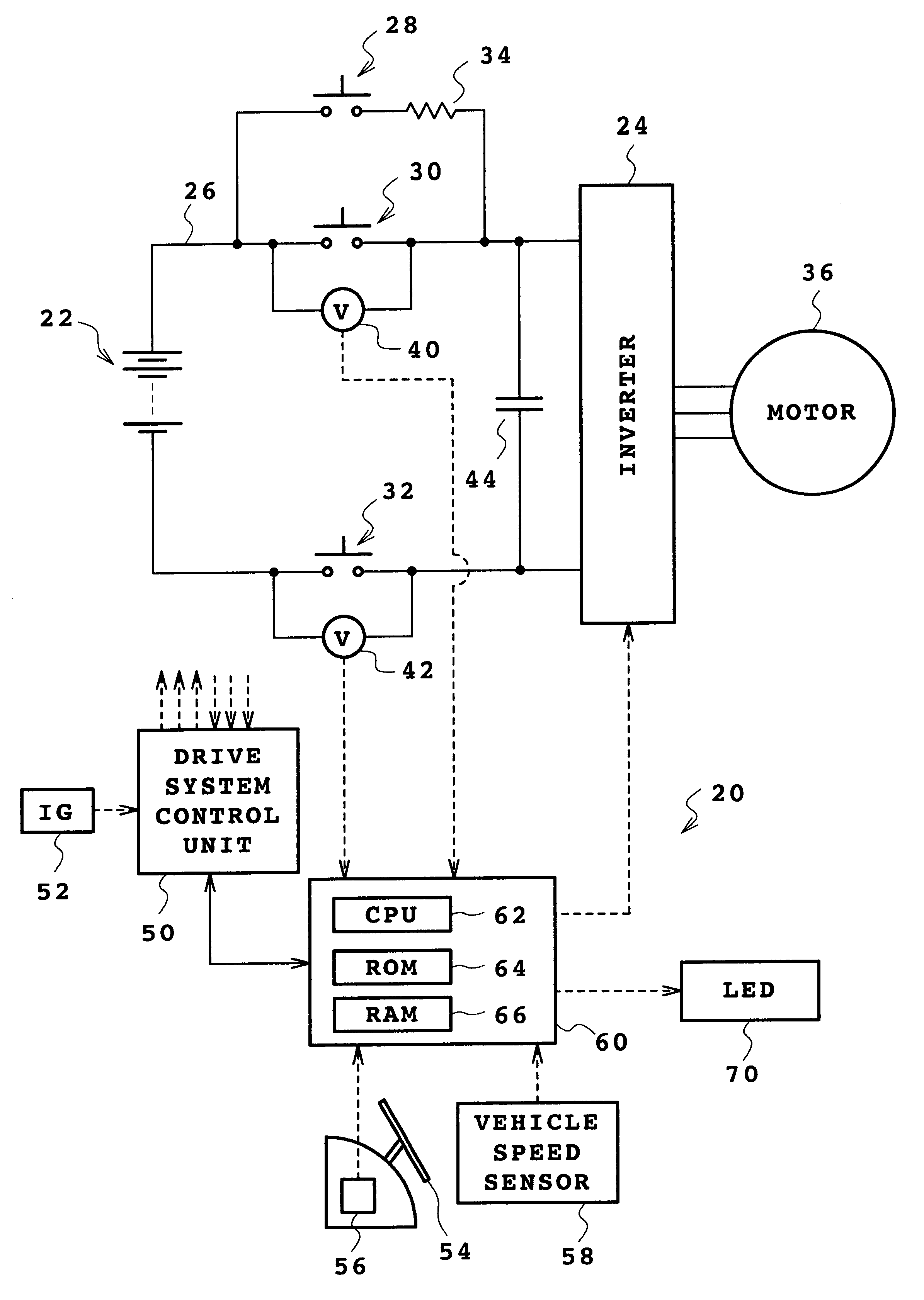
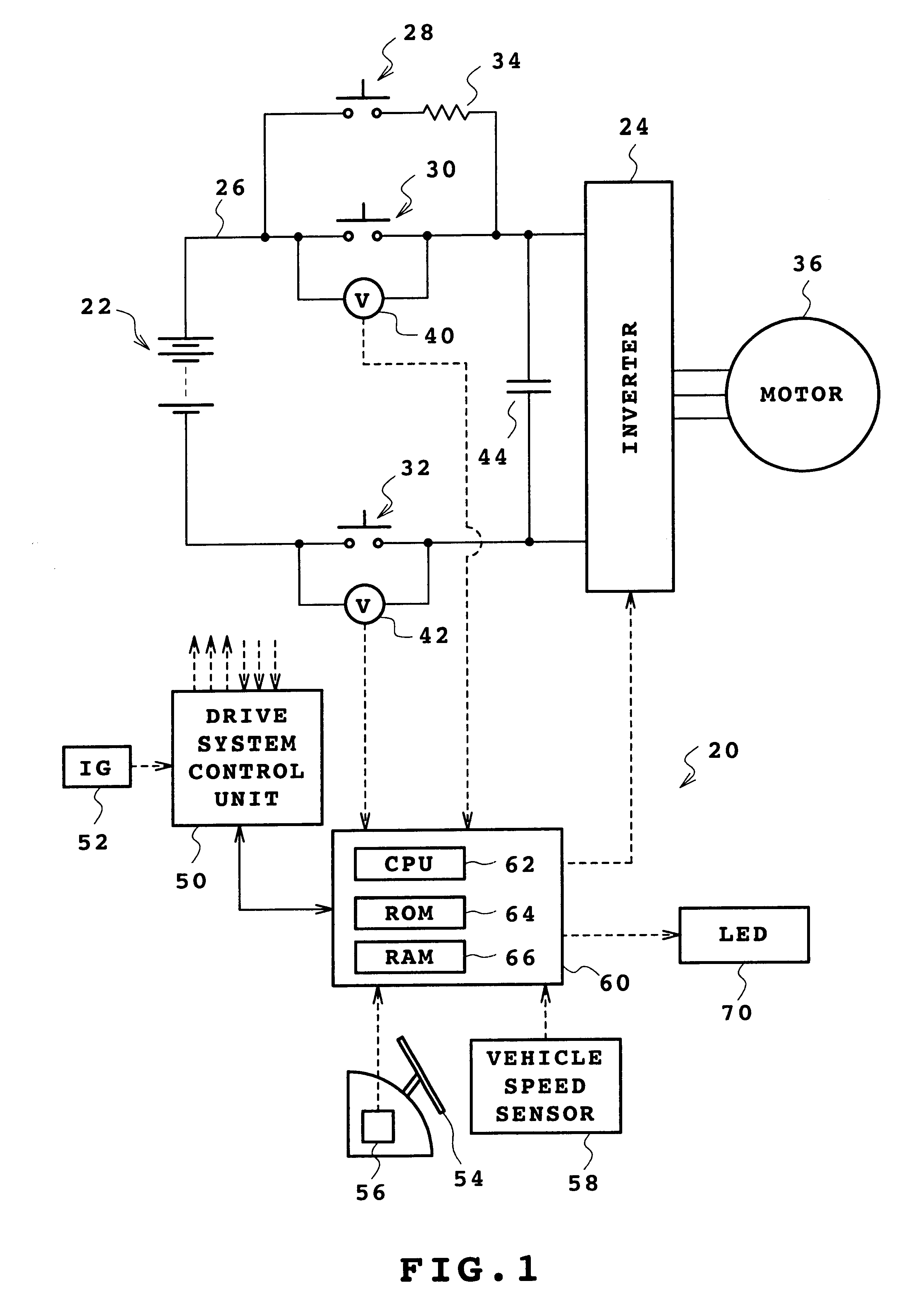
An embodiment of the present invention will be described below. FIG. 1 is a structural diagram schematically showing a structure of a drive system provided with a battery 22 and a motor 36 which are mounted on an electric vehicle to which the relay welding detector 20 according to one embodiment of the invention is applied. The drive system mounted on the electric vehicle will first be described.

As shown in FIG. 1, this drive system is configured to supply power from the battery 22 to the motor 36 after converting it into a three-phase alternating current suitable for driving the motor 36 by an inverter 24. Relays 28, 30, 32 which connect or disconnect the electric power from the battery 22 to the motor 36 are disposed on a power line 26 which is connected to an output terminal of the battery 22. The relay welding detector 20 of the embodiment detects welding of the relays 30, 32. A capacitor 44 is connected to the power line 26 running between the relays 28, 30, 32 and the inverter...


PUM

PropertyMeasurementUnit
discharging poweraaaaaaaaaa
electric currentaaaaaaaaaa
currentaaaaaaaaaa

Abstract

Frequency of judgment of welding of relays is increased to increase likelihood of early detection of welding. It is determined that a battery 22 is not being recharged or discharged when a vehicle speed V of an electric vehicle is approximately 0 and a brake pedal 54 is pressed, and a switching element of an inverter 24 is controlled to be switched to discharge electric charges which are stored in a capacitor 44. After discharging, relays 30, 32 are turned off, and voltages RV1, RV2 between the terminals of the relays 30, 32 are detected by voltmeters 40, 42 to judge whether either of the voltages RV1, RV2 has a threshold value RVref (approximate value 0) or less. When it is so determined, it is judged that the relays 30, 32 are welded, and an LED 70 is illuminated.

Description

1. Field of the InventionThe present invention relates to a relay welding detector, and more particularly to a relay welding detector for detecting welding of a relay which is disposed between a switching element and a secondary battery in a system for supplying power from the secondary battery to a load through the switching element and which connects or disconnects a power line running from the secondary battery to the load.2. Description of the Related ArtThere has been proposed a relay welding detector and detecting method which detects welding of a relay when operation of an electric motor is started or stopped by operation of a key switch (e.g., Japanese Patent Laid-Open Publication No. Hei 10-144194). In that detector, a terminal voltage of the electric motor is detected in a relay off state immediately before the operation of the electric motor is started by an operator who turns on the key switch, or a state that the operation of the electric motor is stopped and the relay ...

Claims


Application Information

Patent Timeline
Patent Type & Authority Patents(United States)
IPC IPC(8): B23K31/02H01H47/00H02H7/00B60L3/00H01H47/32H02P27/06
CPCB23K31/02H01H47/002B23K2201/36B23K2101/36
Inventor MATSUKI, TSUTOMUKATSUDA, TOSHIHIRO
Owner TOYOTA JIDOSHA KK
Why Eureka
Try Eureka