Image registration system and method

a technology of image registration and image, applied in the field of diagnostic image processing, can solve the problems of affecting the application of vision correction, affecting the accuracy of image recognition,

Inactive Publication Date: 2003-12-02
BAUSCH & LOMB INC
View PDF3 Cites 41 Cited by
  • Summary
  • Abstract
  • Description
  • Claims
  • Application Information

AI Technical Summary

Problems solved by technology

This is a relatively long time frame in relation to the saccadic movement of the eye and the time it takes for a person to change their gaze during a measurement sequence.
Voluntary or involuntary eye motion may cause a particular measurement parameter to be inaccurately recorded and a resulting vision correction application to be less than optimal.

Method used


Image

  • Image registration system and method
  • Image registration system and method
  • Image registration system and method

Examples


Embodiment Construction

The embodiments of the invention will be described in detail below with reference to the accompanying figures wherein like reference numerals refer to similar references throughout.

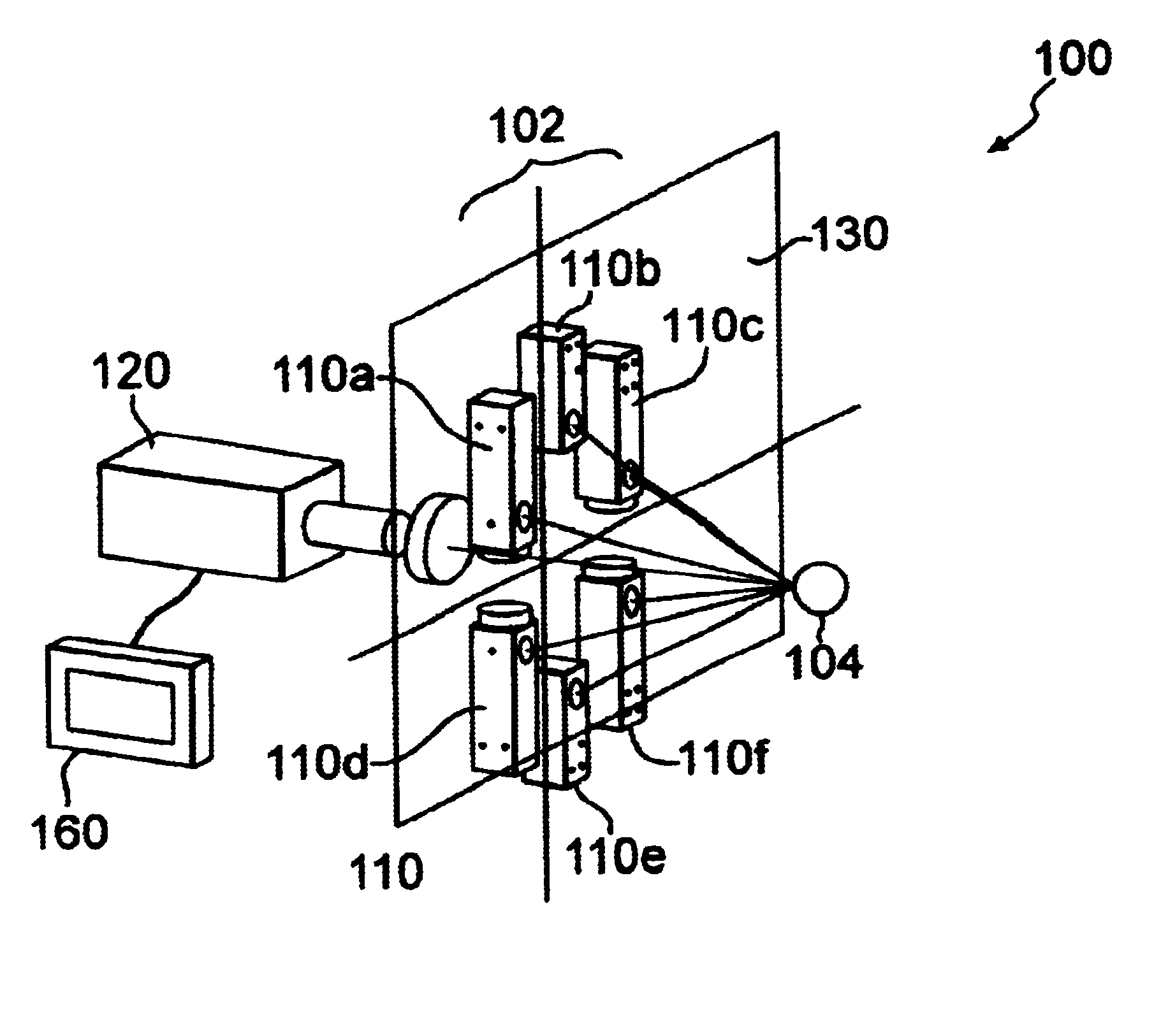
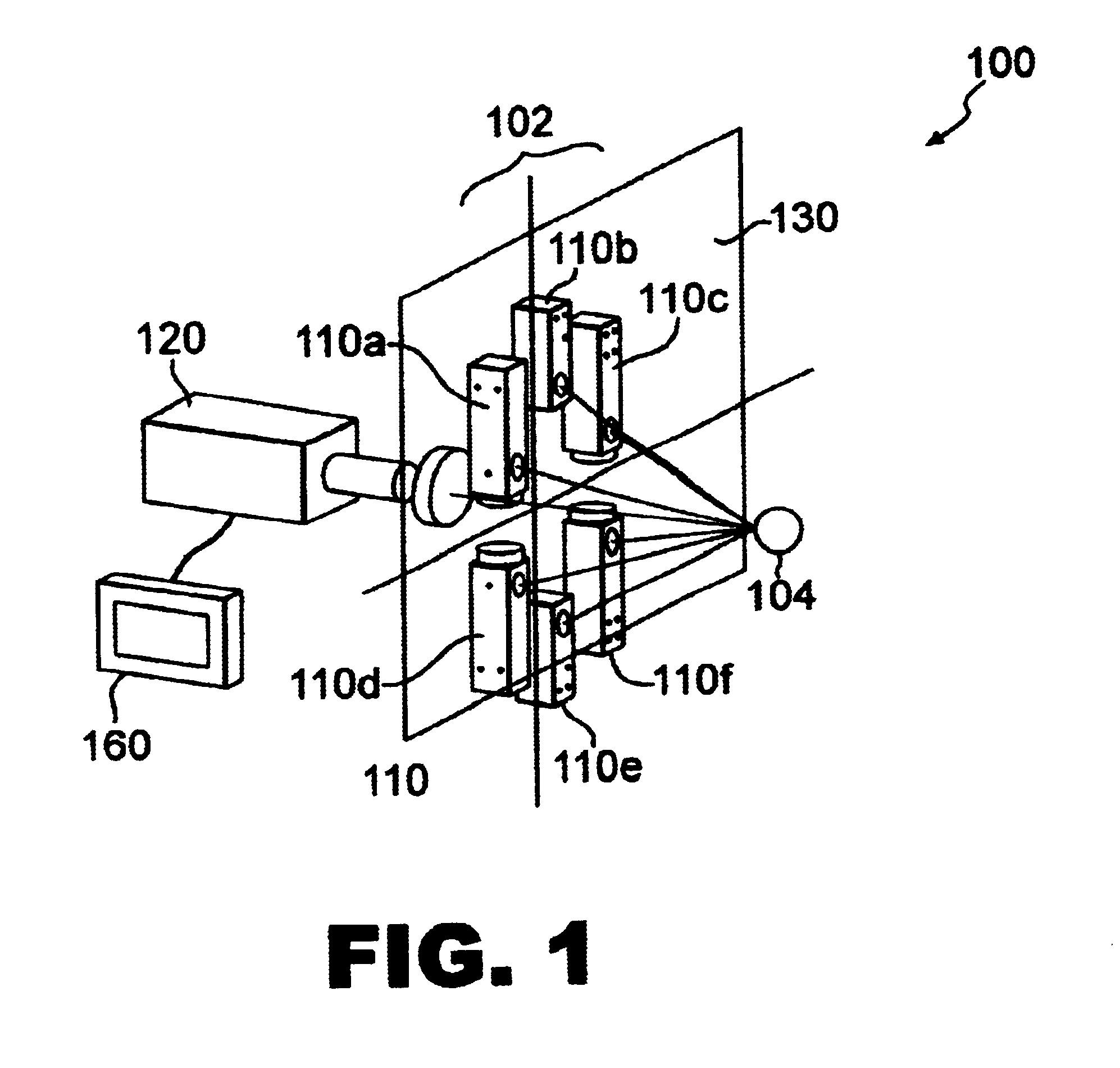
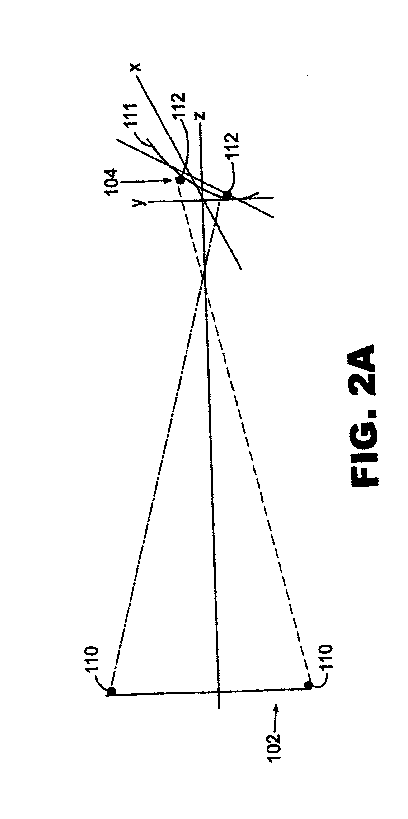
FIG. 1 illustrates a preferred embodiment of a system 100 for monitoring the spatial position, and tracking the movement of, the corneal surface 104 of a patient's eye which by definition is spherical or quasi spherical. FIG. 1 also represents an image registration system 100 for registering multiple images of a spherical or quasi spherical object surface such as the cornea of the eye. The system and device 100 generally comprises a projection component 102 (as shown in FIG. 2), an image capture component 120 and a computing component 160 operably connected to the image capture component 120. As shown in FIGS. 2a and b, the projection component 102 includes at least one light-emitting element 110, and the projection component projects at least four spots of light 112a-d onto the (spherical or quasi-spheri...


PUM


Abstract

An apparatus for registering a series of video images of a spherical or quasi-spherical surface subject to movement relies on projecting at least four diffusely scattering spots of light on the surface in a preferred angular manner, and monitoring the movement of images of the light spots relative to a reference image of the light spots.

Description

1. Field of the InventionThe invention is generally directed towards diagnostic image processing, and, more particularly to a device and system for position and motion sensing of a spherical object surface, and to a method for detecting such motion and registering a series of temporal image frames of the object surface.2. Description of Related ArtThe first step in any ophthalmic procedure is to diagnose the pathology of the eye and / or characterize its structure. In the field of refractive surgery for correcting defective vision of a person's eye, it is important to gather accurate information about the topography and pachymetry of the eye as well as the nature and magnitude of the aberrations that cause poor vision. The gathering of this diagnostic information typically requires the patient to engage some type of instrument and steadily view a target while the diagnostic information is acquired, usually through multiple video images taken over a time interval ranging from fractions...

Claims


Application Information

Patent Timeline
Patent Type & Authority Patents(United States)
IPC IPC(8): A61B3/113
CPCA61B3/113
Inventor EAGAN, BARRYCALDWELL, LLOYD M.CADY, D. ROBERTGROVE, DONALD C.NIVEN, GREGG D.NGUYEN, XAN
Owner BAUSCH & LOMB INC
Why Eureka
Try Eureka