Proton exchange membrane fuel cell external manifold seal

a fuel cell and proton exchange membrane technology, applied in the field of manifold seal system, can solve the problems of csa and manifold-to-csa seals undergoing compressive creep, increasing reactant leakage, and general damage of proton exchange membranes, and achieves compressible effect and low creep

Inactive Publication Date: 2003-12-09
AUDI AG
View PDF8 Cites 26 Cited by
  • Summary
  • Abstract
  • Description
  • Claims
  • Application Information

AI Technical Summary

Benefits of technology

The invention provides an effective seal to the fuel cell for all pressure differentials experienced by the seal during fuel cell operation, without leaking, and does not require periodic tightening of a manifold to maintain the seal over time. The sealing system of the invention allows easy removal of the manifold, should it be required.

Problems solved by technology

Also, during operation of the CSA, the CSA and the manifold-to-CSA seals undergo compressive creep.
Thus, since the CSA is made up of a series of cells, the edges of which are not aligned, and the surface of the stack is therefore rough, compressive creep of the stack and the manifold-to-CSA seals results in increased reactant leakage.
Since the proton exchange membrane is generally damaged above about 150.degree. C.
), curing the prior seal compound would destroy a PEM fuel cell.
However, this material exhibits poor springback characteristics, resulting in increased leakage as a function of time and a requirement to continuously tighten the manifolds.

Method used


Image

  • Proton exchange membrane fuel cell external manifold seal
  • Proton exchange membrane fuel cell external manifold seal
  • Proton exchange membrane fuel cell external manifold seal

Examples


Embodiment Construction

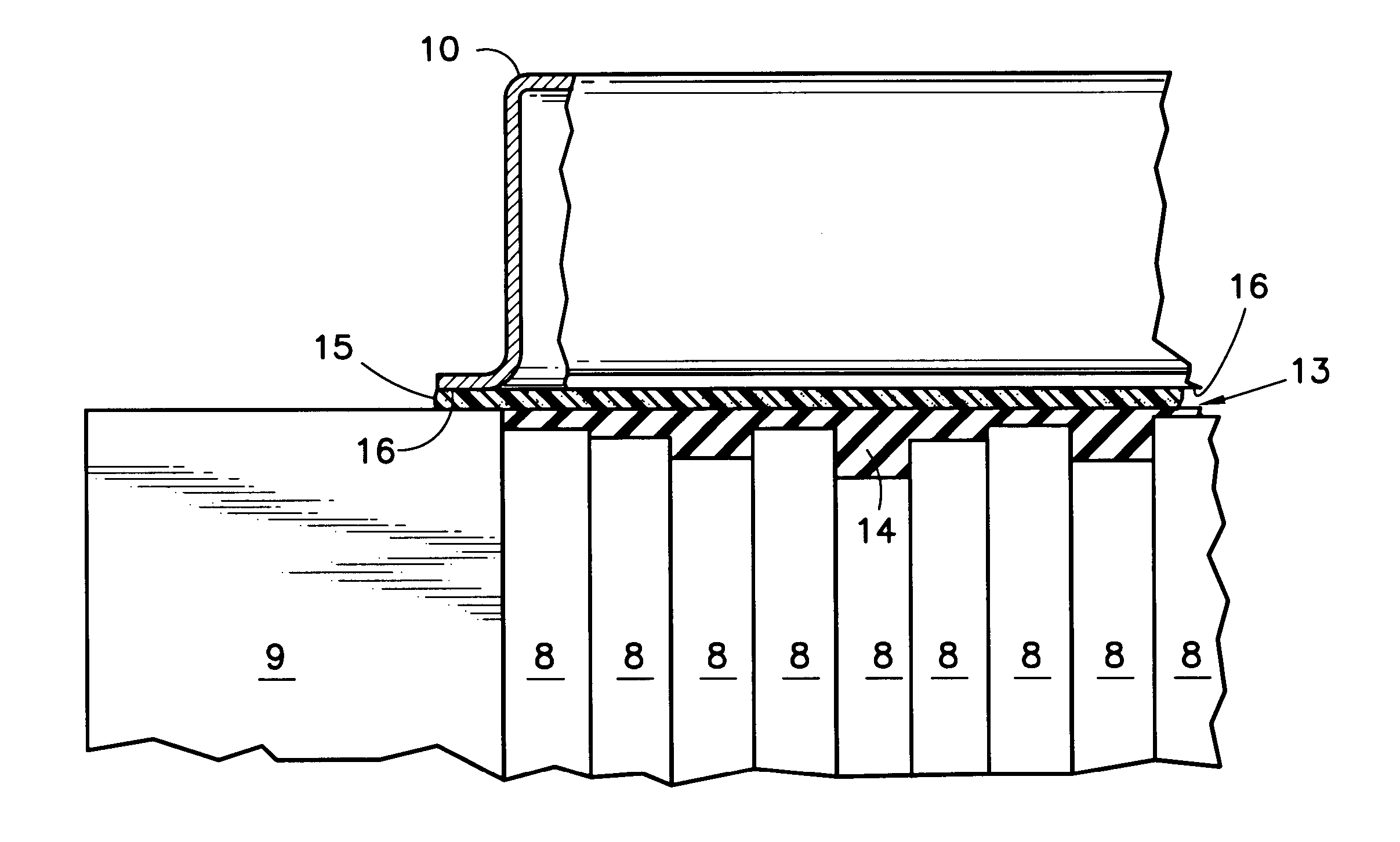
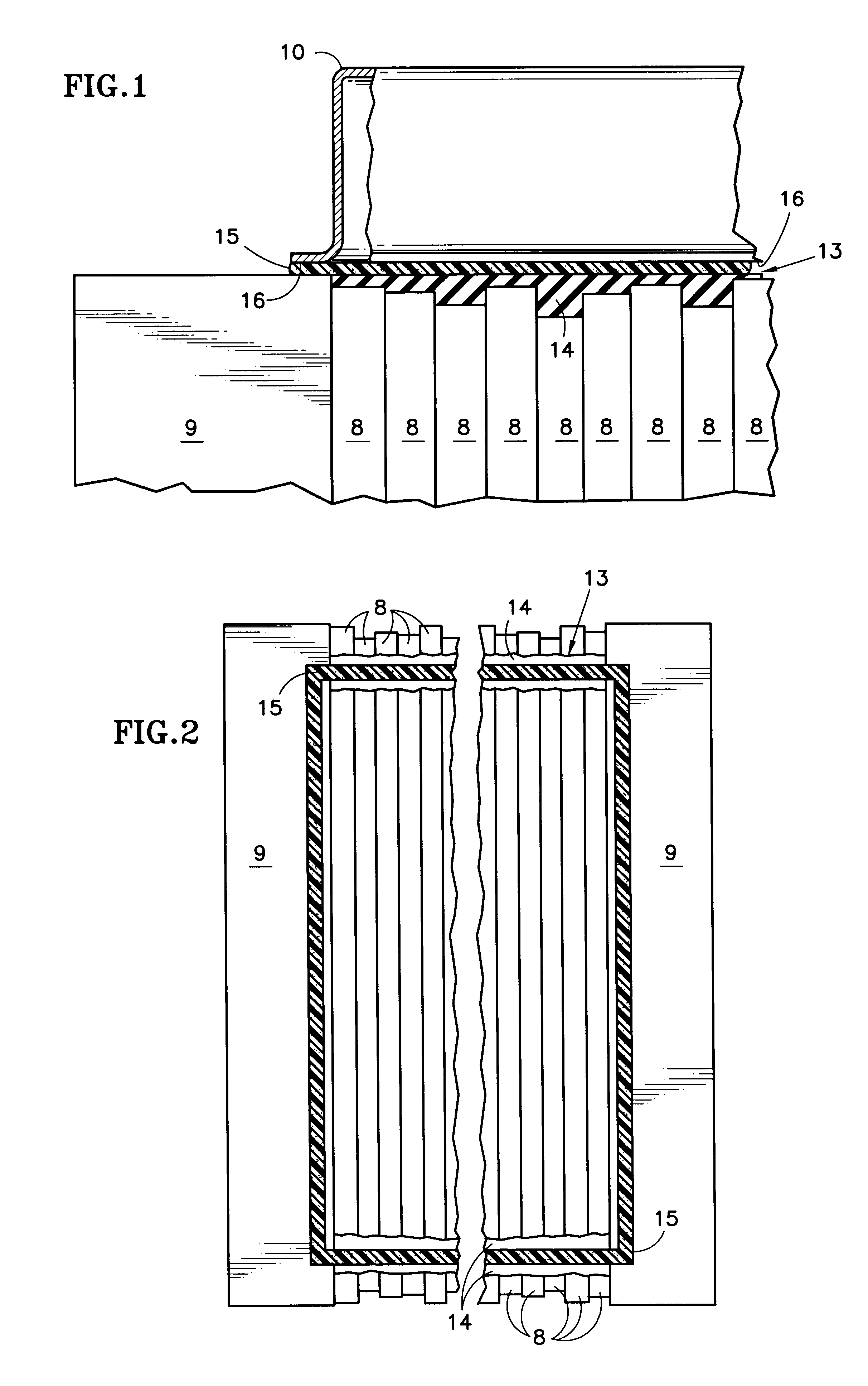
Referring to FIGS. 1 and 2, the fuel cell component elements 8 of a PEM fuel cell are depicted stylistically, and, as is known include, for each cell, a membrane, an anode substrate, an anode catalyst, a cathode substrate, a cathode catalyst, an anode flow field plate and a cathode flow field plate; a cooler plate may be interspersed between each cell or each group of three to four cells. The positions of the edges of these elements are irregular as shown in FIG. 1, giving rise to one aspect of the problem with providing an adequate seal system for a PEM fuel cell. The elements 8 are sandwiched between end plates 9, which are bolted together so as hold the various layers in tight contact with one another. A reactant gas manifold 10 (shown in FIG. 1) is positioned above the elements 8 so as to provide flow of reactant gas (either oxygen containing oxidizing gas or hydrogen containing fuel gas) to and from the flow field plates so as to bring the reactant gases to the anode and cathod...


PUM

PropertyMeasurementUnit
compressive setaaaaaaaaaa
stack temperaturesaaaaaaaaaa
pressureaaaaaaaaaa

Abstract

A sealant system 13 for a manifold 10 of a proton exchange membrane fuel cell includes low temperature cured or heat cured silicone rubber bridges 14, 14a, 14c between the end plates 9 to compensate for the uneven edges of various fuel cell component layers, and a layer 15 of silicone rubber foam or sponge, or a molded silicone rubber gasket 15a, extending across the bridges and along the end plates, around the entire contact perimeter surfaces of the manifold, to seal the manifold to the fuel cell. The cured silicone rubber may extend along the end plates between the bridges. A rubber strip 20 may be adhered to the silicone rubber bridges and end plates. The bridges may comprise a first layer 22 of low shrinkage self-leveling RTV liquid rubber with viscosity in the range of 10,000-20,000 cps and a second layer 14 of RTV liquid rubber.

Description

This invention relates to a multi-part rubber / elastomer seal system for a proton exchange membrane (PEM) fuel cell reactant gas manifold.A basic fuel cell comprises an anode electrode spaced apart from a cathode electrode with an electrolyte disposed therebetween in a compartment formed between the two electrodes; each electrode also includes a catalyst layer on the electrolyte side thereof. On the non-electrolyte side of the anode electrode is a reactant gas chamber for carrying a fuel, and on the nonelectrolyte side of the cathode electrode is a reactant gas chamber for carrying an oxidant. The electrodes are constructed so that the gas diffuses therethrough and comes into contact with the electrolyte in the catalyst layer thereby causing a well-known electrochemical reaction whereby hydrogen ions and electrons produced at the anode travel from the anode electrode through, respectively, the electrolyte and the external circuit to the cathode electrode where they react with oxygen ...

Claims


Application Information

Patent Timeline
Patent Type & Authority Patents(United States)
IPC IPC(8): H01M8/02H01M8/24
CPCH01M8/0271H01M8/2485Y10T29/4911Y02E60/50H01M2300/0082
Inventor KRASIJ, MYRONDUFNER, BRYAN F.MARTIN, RONALD G.
Owner AUDI AG
Why Eureka
Try Eureka