Ink-jet head base board, ink-jet head, and ink-jet apparatus

a technology of inkjet head and inkjet head, which is applied in the field of inkjet head base board, inkjet head and inkjet apparatus, which can solve the problems of chemically affecting the ink itself, the proportion and the intense heat of the inkjet head

Inactive Publication Date: 2003-12-16
CANON KK
View PDF11 Cites 20 Cited by
  • Summary
  • Abstract
  • Description
  • Claims
  • Application Information

AI Technical Summary

Benefits of technology

Ink-jet recording apparatuses are distinctive in that they can print highly precise images at a high speed by ejecting ink in the form of a microscopic droplet from orifices. Recently, such ink-jet recording apparatuses that employ electrothermal transducers, which have a portion formed of exothermic resistant material, as a means for generating the energy used for ejecting ink, and that use the bubbling, that is, boiling, or ink caused by the thermal energy generated by the electrothermal transducers, have been attracting attention, because they are particularly suitable for forming high precision images, are capable of recording at a high speed, and make it possible to reduce in size, and / or colorize a recording head as well as a recording apparatus (for example, those disclosed in U.S. Pat. Nos. 4,723,129 and 4,740,796).
Thus, this thermally interactive portion of the ink-jet head is generally covered with a top portion protecting layer for protecting the electrothermal transducer from the cavitation shocks, and also for preventing ink from chemically affecting the electrothermal transducer.

Problems solved by technology

When ink is ejected, the portion of the ink-jet head, which thermally interacts with ink, is subjected to not only the intense heat generated by the exothermic resistant material, but also the shocks (cavitation shocks) caused by the formation and collapsing of ink bubbles.
Also, it is chemically affected by the ink itself.
After reaching its peak, it began to fall due to heat dissipation.
This is due to the fact that the thicker the protective layer, the longer the time necessary for the damage or corrosion to reach the exothermic resistant layer, and therefore, the longer the service life of the head.
When such improved ink, in particular, ink which contains ingredients, such as Ca and Mg, capable of forming bivalent metallic salt, or chelate complex, is used, the protective layer tends to be corroded through a thermochemical reaction which occurs between the protective layer and ink.
However, increasing the thickness of the protective layer results in the reduction in the efficiency with which the thermal energy generated in the exothermic resistant layer conducts to the thermally interactive surface.
However, if the protective layer is reduced in thickness, the damages caused to the thermally interactive portion by the cavitation shock and / or the corrosive effect of ink, reach the exothermic resistant layer more quickly than when the protective layer is not reduced in thickness, although this depends upon the type of the protective layer material.
In other words, reducing the thickness of the protective layer is detrimental to the extension of the service life of the head.
Further, driving the head with a pulse with a shorter width causes the protective layer to be subjected to a greater concentration of cavitation shocks generated by the generation and collapse of bubbles in ink in a shorter time.
In terms of the conventional technologies, the problems regarding the increasing the thickness of the protective layer, and this method is limited where the further improvement in thermal efficiency and further increase in recording speed are concerned (when it comes to the matters of further improving the thermal efficiency and further increasing the recording speed).

Method used


Image

  • Ink-jet head base board, ink-jet head, and ink-jet apparatus
  • Ink-jet head base board, ink-jet head, and ink-jet apparatus
  • Ink-jet head base board, ink-jet head, and ink-jet apparatus

Examples


embodiment 1

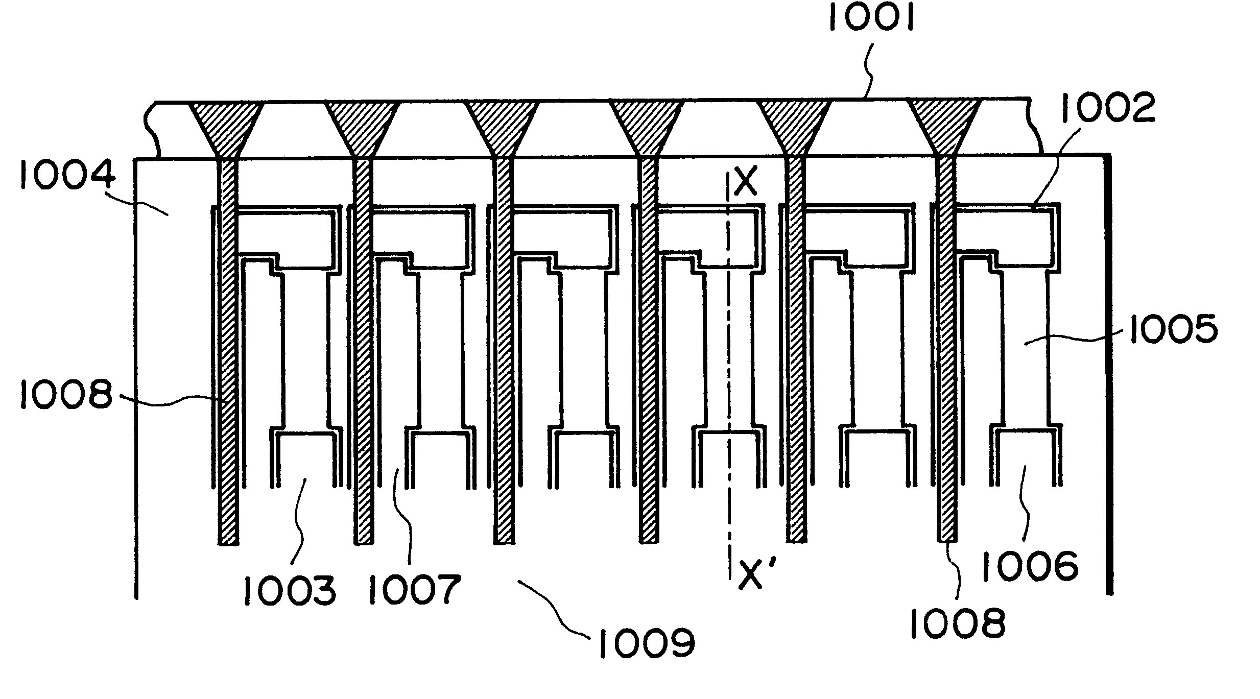
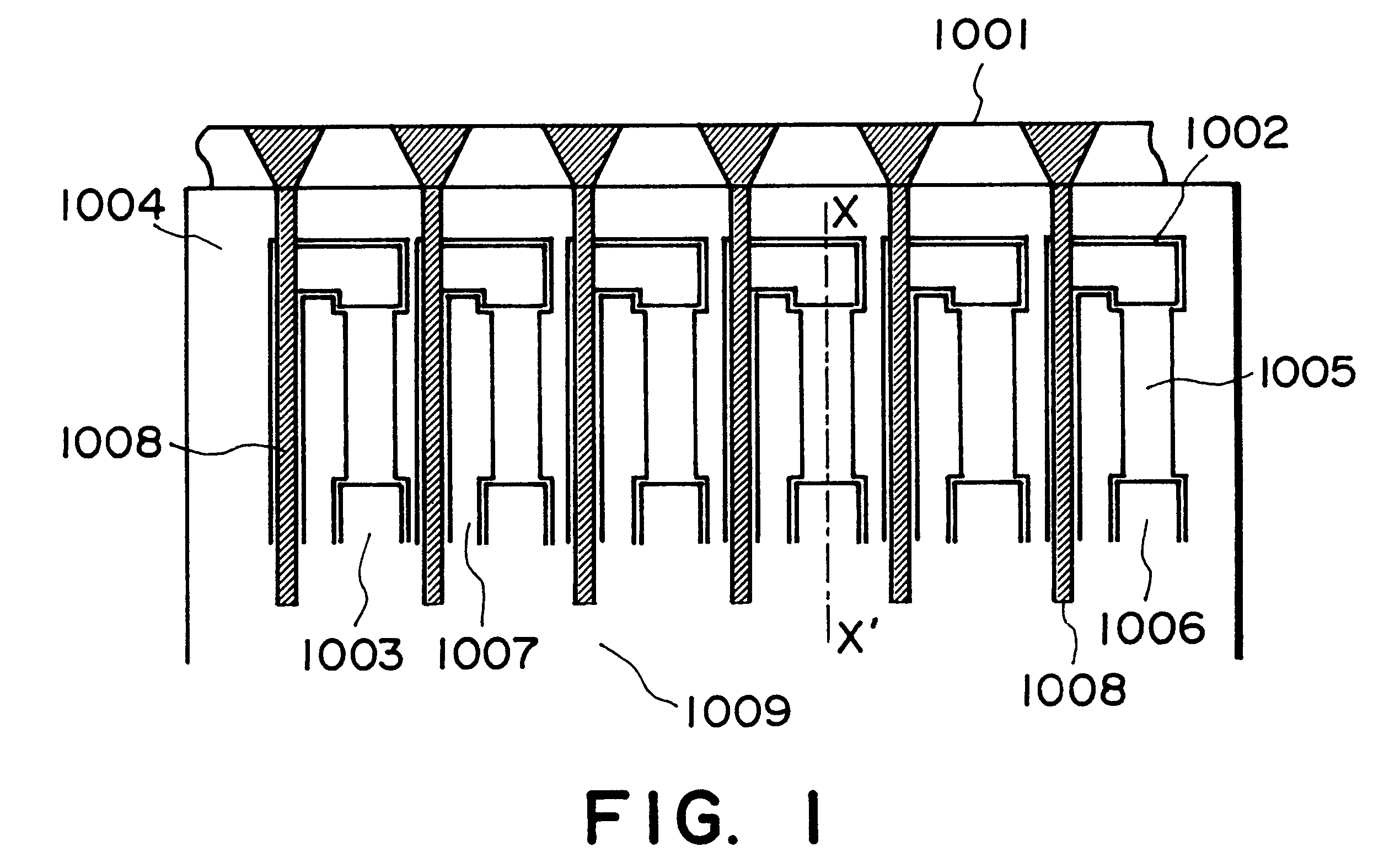
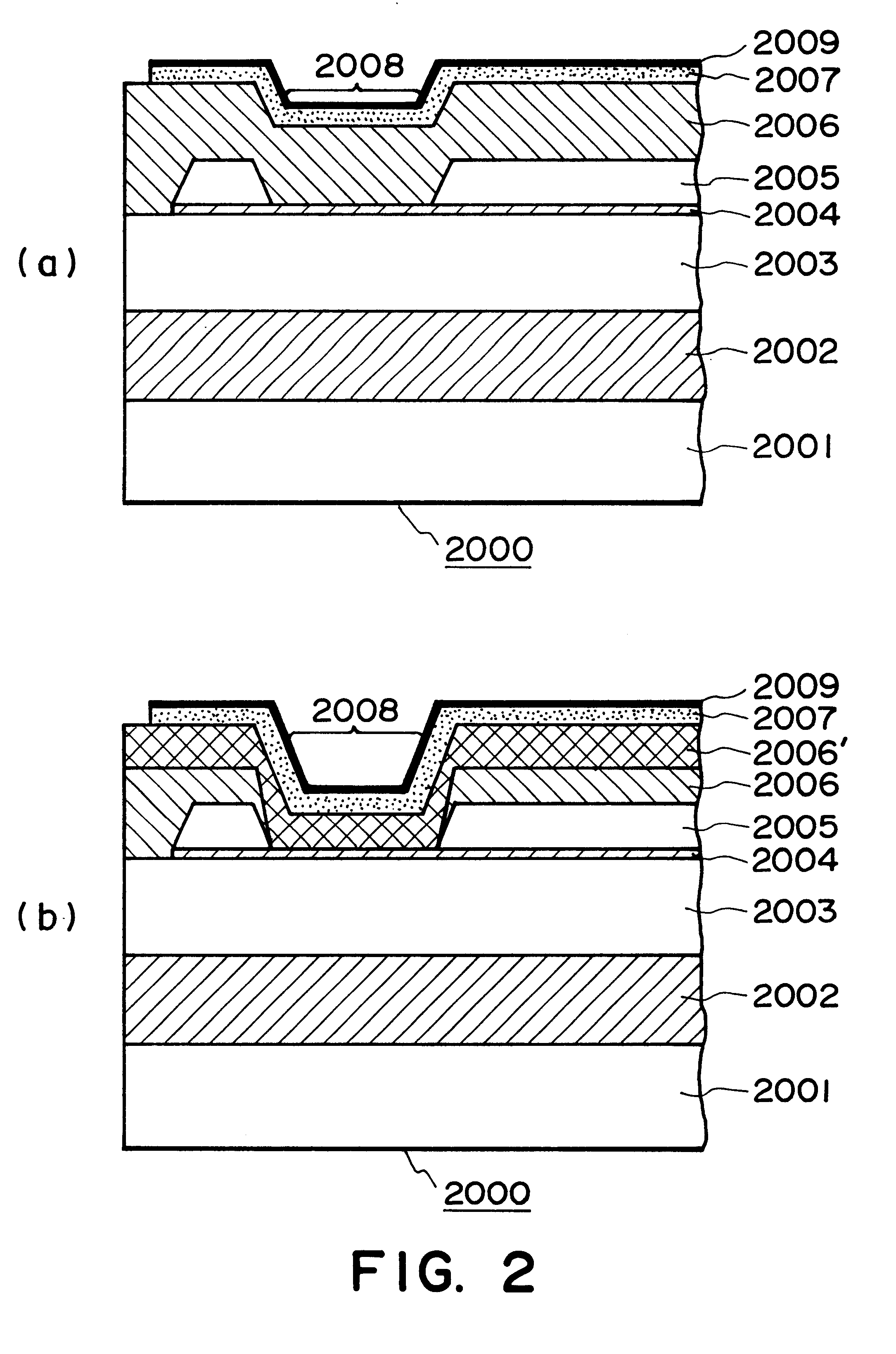
The substrate of the samples evaluated to determine the characteristics of the ink-jet in this embodiment was a piece of plane Si substrate, or a piece of Si substrate on which a driver IC had been already built in. In the case of the plane Si substrate, the heat storage layer 2002 (FIG. 2(b) ), that is, a 1.8 .mu.m thick layer of SiO.sub.2, was formed thereon by such a method as thermal oxidization, sputtering, CVD, or the like. In the case of the Si substrate with the IC, the heat storage layer, or the SiO.sub.2 layer, was formed similarly to the case of the Plane Si substrate, during its manufacturing process.

Next, an interlayer insulative film 2003, that is, a 1.2 .mu.m thick film of SiO.sub.2, was formed by sputtering, CVD, or the like methods. Next, the exothermic resistant layer 2004, that is, a 500 nm thick Ta.sub.35 Si.sub.22 N.sub.43 alloy layer, was formed by a method of reactive sputtering using a target formed of Ta--Si alloy. During the formation of this exothermic res...

embodiments 2-5

Ink-jet heads, which were identical to those in the first embodiment except that the top portion protecting layers 2007 were given the compositions and thicknesses shown in Table 2, were produced, and were tested for endurance like those in the first embodiment. The results are given in Table 2.

embodiments 6-9

Ink-jet heads, which were identical to those in the first embodiment except that the top portion protecting layers were formed using a method of sputtering in which a target formed of Ta--Fe--Cr--Ni alloy with a predetermined composition (atomic composition ratio), were used along with argon gas. The top portion protecting layers of these ink-jet heads were given the compositions and thicknesses shown in Table 2. These ink-jet heads were tested for endurance like those in the first embodiment. The results are given in Table 2.

The following became evident from the tests. That is, it became evident from the results given in Table 2, that the length of the printing life of a head depended on the compositional ratios among Ta, Fe, Ni and Cr within the top portion protecting layer, in particular, that the greater the ratio of Fe--Cr--Ni, the longer the length of the printing life of an ink-jet head; in other word, in the composition Ta.alpha.Fe.beta.Ni.gamma.Cr.delta. of the top portion ...


PUM


Abstract

A base member for an ink jet head, the base member comprising a substrate, a heat generating resistor provided between electrodes which constitute a pair on the substrate an upper protection layer provided on an insulation layer which in turn is provided on the heat generating resistor, the upper protection layer having a contact surface contactable to ink, the improvement residing in thatthe upper protection layer is made of amorphous alloy having a following composition formula:where 10 atomic %<=alpha<=30 atomic %, alpha+beta<80 atomic % alpha<beta, delta>gamma and, alpha+beta+gamma+delta=100 atomic %, and, at least the contact surface of the upper protection layer contains an oxide of a constituent component.

Description

FIELD OF THE INVENTION AND RELATED ARTThe present invention relates to a base board for forming an ink-jet head (hereinafter, it may be referred to "head" for simplicity) which prints letters, signs, images, or the like on recording medium such as paper, plastic sheet, fabric, ordinary objects, and the like, by ejecting functional liquid, for example, ink, onto the recording medium. It also relates to an ink-jet head comprising such a base board, a recording unit, for example, an ink-jet pen, comprising an ink storage portion for storing the ink supplied to such an ink-jet head, and an ink-jet apparatus in which such an ink-jet head is installed.There are various configuration for a recording unit, such as an ink-jet pen, in accordance with the present invention. One of such configurations is a cartridge. A cartridge may comprise an integral or independent combination of an ink-jet head and an ink storing portion. An ink-jet recording unit is structured so that it can be removably m...

Claims


Application Information

Patent Timeline
Patent Type & Authority Patents(United States)
IPC IPC(8): B41J2/14B41J2/16B41J2/05B41J2/235
CPCB41J2/14129B41J2/1604B41J2/1646B41J2/1631B41J2/1642B41J2/1623B41J2/235
Inventor SAITO, ICHIROOGAWA, MASAHIKOOZAKI, TERUOKUBOTA, MASAHIKOMOCHIZUKI, MUGA
Owner CANON KK
Why Eureka
Try Eureka