Laser beam detecting device for a construction machine

a technology of laser beam detection and construction machine, which is applied in the direction of vehicle position/course/altitude control, process and machine control, instruments, etc., can solve the problems of detecting device interference with any other portion, deficiency of detection range of beam sensor,

Inactive Publication Date: 2003-12-16
KK TOPCON
View PDF13 Cites 24 Cited by
  • Summary
  • Abstract
  • Description
  • Claims
  • Application Information

AI Technical Summary

Benefits of technology

For example, in the case where there are three reference positions, it is preferable that a central reference position be made a standard position, that offset positions be established one each above and below the standard position, and that position information, which urges movement, be indicated to the operator in the same quantity in the vertical direction. Since not only the central reference position (on-grade position) alone in the laser beam detection range of the laser beam detecting device, but also upper and lower offset positions with respect to the central reference position can be established, it is possible to substantially expand the detection range in the predetermined direction.
The detection range in the predetermined direction can be widened according to contents of a work to be executed without changing the size of the laser beam receiving portion in the beam sensor, and therefore the work can be carried out in a more accurate manner.
Thus, according to the present invention, reference positions can be offset with respect to the predetermined direction without any change in the detection range.
Alternatively, the laser beam detecting device may be fixed magnetically to a leveling implement of a construction machine. In this case, a strong magnetic force can be obtained by holding plural magnets in between plural net plates. In this case there is attained a high durability because the steel plates are in contact with the leveling implement. Besides, since the steel plates are each adapted to move slightly, they can fix the magnets securely and prevent them from coming off even if the magnet surfaces are somewhat uneven or even under an abrupt shock.

Problems solved by technology

Particularly, in a banking or trenching work, the leveling implement shifts largely in the vertical direction, so there occurs a case where the detection range of the beam sensor becomes deficient.
On the other hand, if there is adopted a structure having a wider detectable range of the beam sensor, a beam receiving portion in the laser beam detecting device concerned becomes larger (i.e., longer in the vertical direction) physically, resulting in that when the detecting device is to be attached, for example, to an arm of a construction machine, it is difficult to do so.
Additionally, there arises a danger that the detecting device may interfere with any other portion (e.g. the leveling implement or earth).

Method used


Image

  • Laser beam detecting device for a construction machine
  • Laser beam detecting device for a construction machine
  • Laser beam detecting device for a construction machine

Examples


Embodiment Construction

An embodiment of the present invention will be described hereunder with reference to the accompanying drawings.

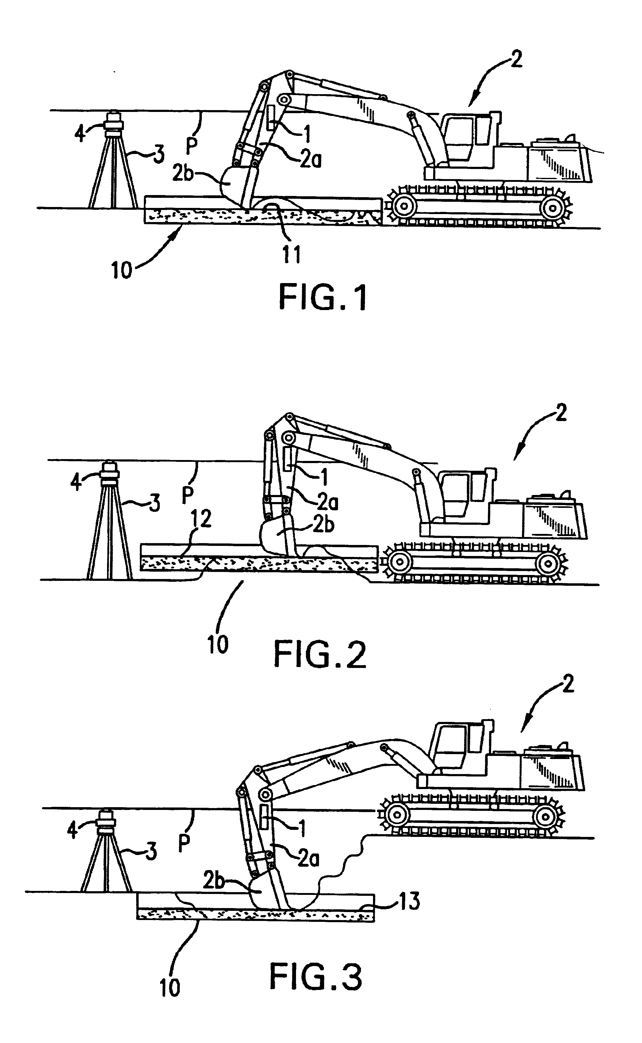
FIGS. 1 to 3 are plan views each showing a state in which a civil engineering work is being carried out by a shovel car 2 equipped with a laser beam detecting device 1 for a construction machine according to the present invention.

FIG. 1 shows an example of an ordinary work, FIG. 2 shows an example of a banking work, and FIG. 3 shows an example of a trenching work.

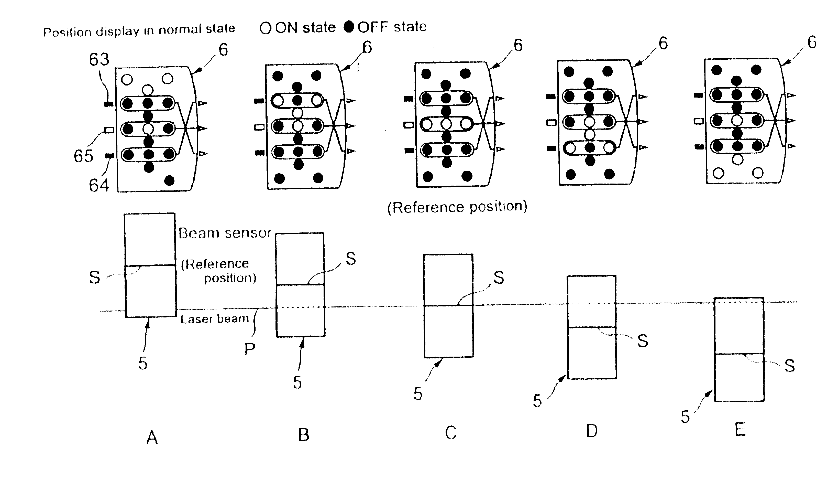
In FIGS. 1 to 3, the reference numeral 10 denotes a detection range of a leveled land (formed land surface).

In the leveled state shown in FIG. 1, a reference position 11 of the leveled land is a standard position.

In the leveled state shown in FIG. 2, a reference position 12 of the leveled land is a first offset position offset upward from the standard position shown in FIG. 1.

In the leveled state shown in FIG. 3, a reference position 13 of the leveled land is a second offset position offset downward from the refere...


PUM


Abstract

In a laser beam detecting device for a construction machine, a beam sensor is installed above a leveling implement of the construction machine, a laser beam is detected by the beam sensor, and information based on the beam detection is displayed on a display. A plurality of reference positions are established in a range in which the beam sensor detects the laser beam. One of the reference positions is made a standard position, while the other reference positions are made offset positions.

Description

The present invention relates to a laser beam detecting device for a construction machine wherein a beam sensor is mounted above a leveling implement, a laser beam for forming a reference plane is detected by the beam sensor, and information based on the detection of the laser beam is displayed on a display.RELATED ARTIn a civil engineering work such as a land formation work for leveling land there is used a construction machine equipped with a leveling implement, such as a shovel car, a bulldozer, or a crawler.Formerly, an operator of a construction machine executed a land formation work with his eye while making a survey repeatedly to check the degree of flatness.Recently, however, with use of a rotating laser, it has become possible for an operator of a construction machine to check the degree of flatness directly on an operator seat. In this case, a laser beam as a reference is detected by a beam sensor mounted above a leveling implement and an offset direction from the referenc...

Claims


Application Information

Patent Timeline
Patent Type & Authority Patents(United States)
IPC IPC(8): E02F9/26E02F3/42E02F3/43E02F9/20G01C15/00G01C15/06
CPCE02F3/437G01C15/006E02F9/26
Inventor OGAWA, YOHEISASAGAWA, JUNYAMADA, HIROKAZUSHIBUYA, HIROTO
Owner KK TOPCON
Why Eureka
Try Eureka