System for controlling cutting horizons for continuous type mining machines

a mining machine and cutting horizon technology, applied in the direction of cutting machines, earthwork drilling and mining, etc., can solve the problems of insufficient data on any current hole for controlling the machine in that current hole, limited coal thickness data recording, and inconvenient use of current hole data for mining machines, so as to increase the efficiency of a continuous type mining machine and increase the efficiency of such efficiency

Inactive Publication Date: 2003-12-23
AMERICAN MINING ELECTRONICS
View PDF11 Cites 83 Cited by
  • Summary
  • Abstract
  • Description
  • Claims
  • Application Information

AI Technical Summary

Benefits of technology

It is an object of the present invention to provide a method and apparatus for increasing the efficiency of a continuous type mining machine.
It is a further object of the present invention t...

Problems solved by technology

However, Lipinsky has determined that mining data on the use of the gamma detectors in Lipinky's invention is limited in significant ways.
Lipinsky has determined that using data on any current hole for controlling the machine in that current hole is inadequate and not useful, due to the fact that no one has derived a good control scheme to predict what is ahead of the miner.
Entry and roadway driving, along with room...

Method used


Image

  • System for controlling cutting horizons for continuous type mining machines
  • System for controlling cutting horizons for continuous type mining machines
  • System for controlling cutting horizons for continuous type mining machines

Examples


Embodiment Construction

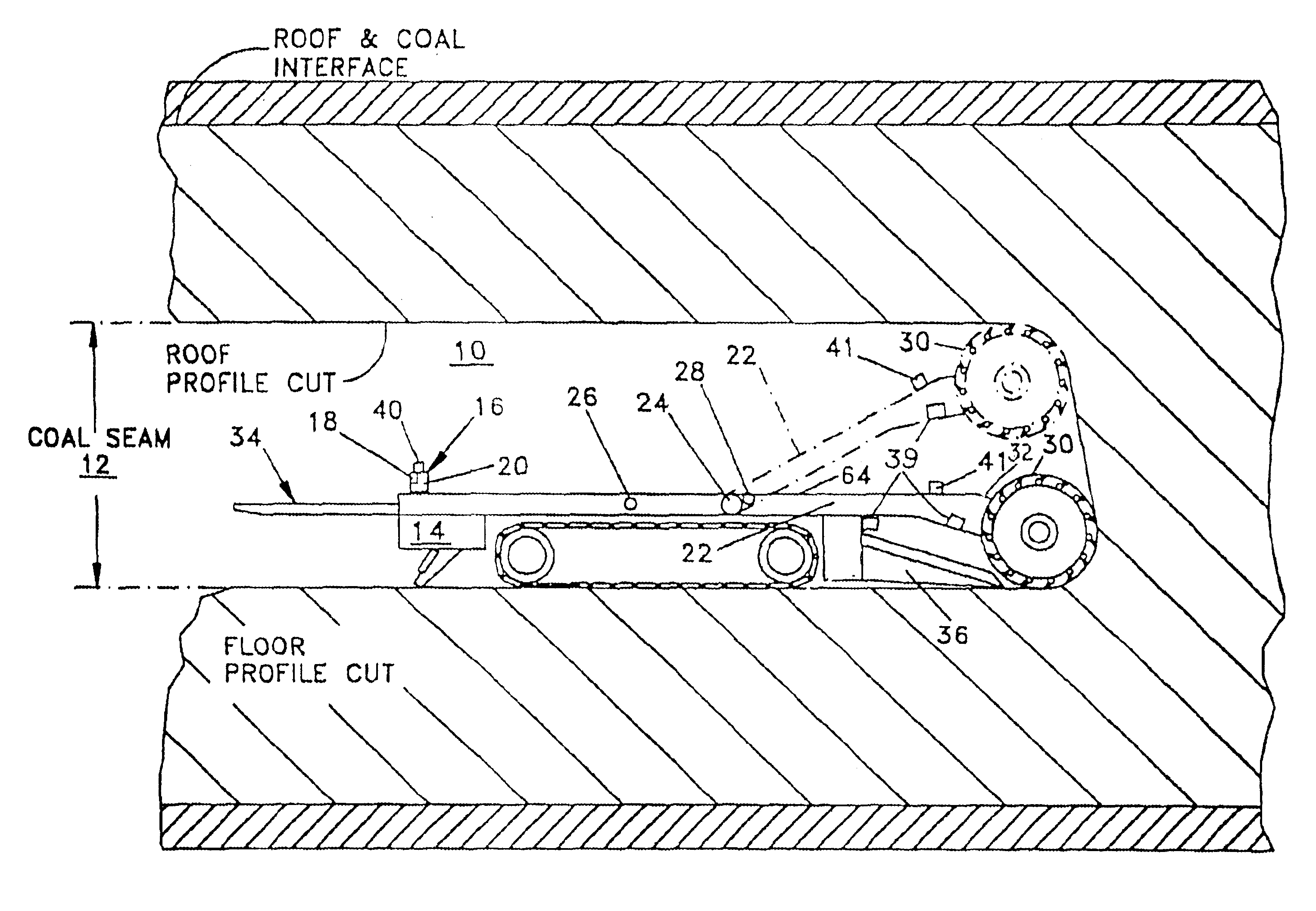
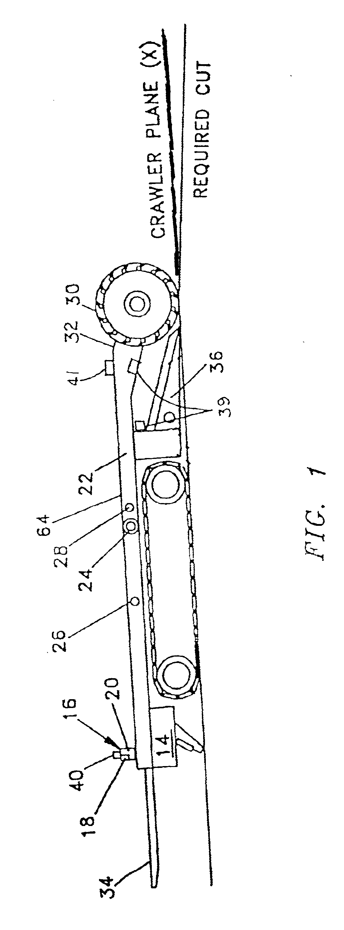
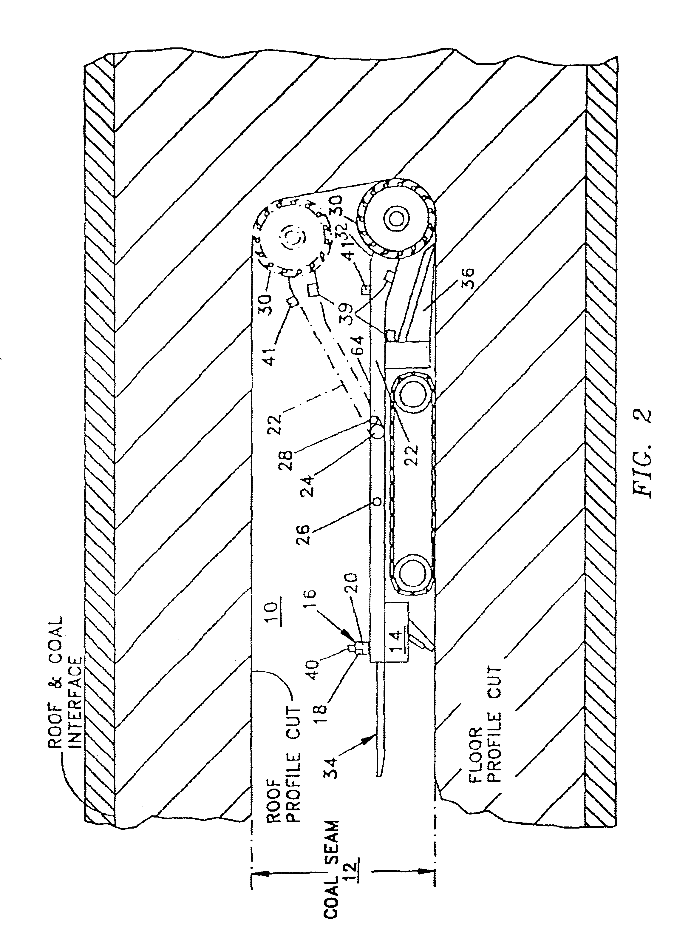
As seen in FIGS. 1 and 2, a tunnel 10 is cut through a coal seam or ore vein 12 by a continuous mining machine 14. The mining machine is referred to as a continuous mining machine since it continuously moves forward through the seam or vein by means of successive sump and cut cycles.

The continuous mining machine 14, typically includes a cutter arm 22 which is pivotally mounted to machine 14 at pivot 24 for up and down movement around the pivot 24. A rotary cutter 30 is mounted on the distal end 32 of arm 22 for removing coal / ore from the seam, and as the coal / ore is being cut it is carried behind the machine by a conveyor system designated by the numeral 34, having a shovel and gathering head 36 at the forward end thereof.

A horizon control system is installed on a continuous mining machine 14, and typically includes the following components as shown in FIGS. 1, 2 and 3. A Master Display and Processor Unit 16, including a display 18 and a processor 20 which provides the intelligence ...


PUM


Abstract

A control system for continuous mining machine to control the mining horizons of roof and floor horizons relative to the rock boundaries of an underground coal seam or ore vein. The mining machine is provided with a cutting drum mounted on a pivoted arm to allow for vertical displacement of the cutter to control the mining height. A plurality of sensors is carried on the rotatable arm to locate the roof and floor boundaries. Attitude sensors are mounted on the machine for providing signals indicative of the inclinations of the body of the machine, and, a microprocessor receives the signals from the boundary sensors and the attitude sensors for calculating the required roof cut and floor cut. A display device receives the signals from the microprocessor and displays the calculated results to the machine operator.

Description

FIELD OF THE INVENTIONThis invention relates to continuous mining machines engaged in the process of extracting mineral, i.e. coal, trona, etc., from an underground seam. More particularly this invention relates to methods and apparatus employed to detect the location of seam boundaries and to guide the machine to achieve the desired cutting horizons (vertical elevations) relative to those seam boundaries.BACKGROUND OF THE INVENTIONContinuous mining machines typically include a self-powered, tracked vehicle having a rotary arm pivotally mounted at its forward end. A cutter is rotatably mounted at the distal end of the rotary arm to cut into a coal or ore seam for extraction of the coal or ore by an extraction mechanism provided on the machine.Various patents exist which describe devices utilized in the mining of coal. Most notably the Lipinsky U.S. Pat. No. (4,952,000) which describes the method and apparatus of HIWALL mining. Lipinsky relies on gamma ray detection as a sensor. Howe...

Claims


Application Information

Patent Timeline
IPC IPC(8): E21C27/24E21C35/08E21C27/00E21C35/00
CPCE21C35/08E21C27/24
Inventor PEASE, ROBERT E.RAMSDEN, JR., JOHN W.
Owner AMERICAN MINING ELECTRONICS
Why Eureka
Try Eureka