Check patentability & draft patents in minutes with Patsnap Eureka AI!

RTD assembly, and temperature sensing system and excitation control system employing an RTD assembly

a technology of temperature sensing system and assembly, which is applied in the field of resistive temperature detector (rtd) temperature sensing, can solve the problems of reducing creapage and clearance, and difficult to obtain the high pot voltage required by the rtd

Inactive Publication Date: 2003-12-23
BASLER ELECTRIC
View PDF11 Cites 39 Cited by
  • Summary
  • Abstract
  • Description
  • Claims
  • Application Information

AI Technical Summary

Benefits of technology

This solution simplifies assembly, maintains high voltage isolation, and reduces installation time by eliminating metal components, ensuring reliable temperature sensing without affecting creepage and clearance, and enhancing robustness against thermal and mechanical stress.

Problems solved by technology

A problem with such metal cases is that they reduce the creapage and clearance of the thyristor bridge with respect to ground and also make it difficult to obtain a high pot voltage required by the RTD.

Method used


Image

  • RTD assembly, and temperature sensing system and excitation control system employing an RTD assembly
  • RTD assembly, and temperature sensing system and excitation control system employing an RTD assembly
  • RTD assembly, and temperature sensing system and excitation control system employing an RTD assembly

Examples


Embodiment Construction

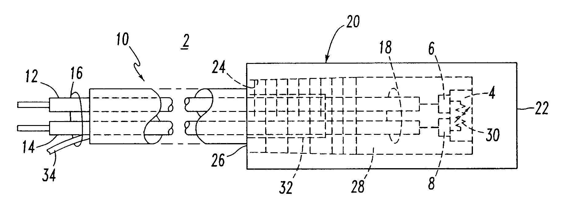
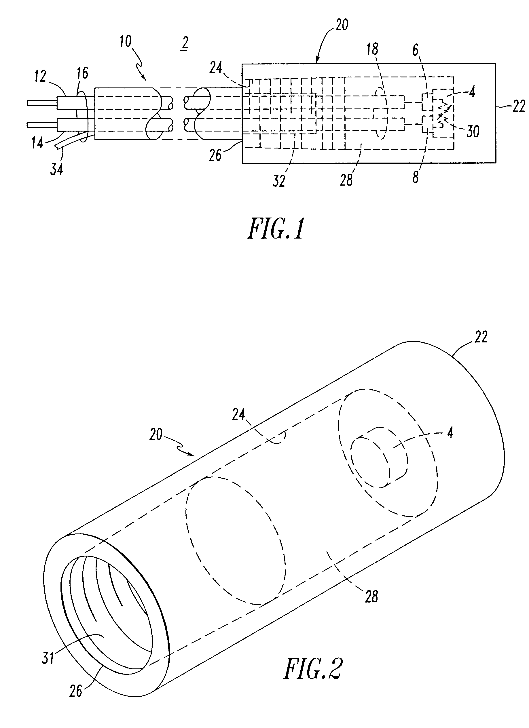
The exemplary RTD 4 is a platinum, 100 .OMEGA. @ 0.degree. C., alpha curve=0.00385.+-.0.12%.OMEGA. @ 0.degree. C., 2 wire, single thin film element. The outputs 6,8 of the RTD 4 have a temperature dependent resistance 30 therebetween. The exemplary electrically insulating body 4 is made of solid polytetrafluoroethylene (PTFE) (e.g., Teflon.RTM.) having a cylindrical shape. This material is rated to about 260.degree. C. and has a diameter of about 0.345 in..+-.0.001 in. and an overall length of about 1.50 in. The cavity 24 has a generally cylindrical shape, which is formed by drilling the body 4 with about a 1.125 in. deep, about 0.166 in. center line hole, and leaving the process end 22 closed and the cold end 26 open. The open (cold side) end 26 is tapped 10-32 at the open end 31 of the cavity 24, which advantageously provides potting grooves. The RTD 4 is inserted at the bottom (toward the right side of FIG. 1) of the cavity 24, at a position which is about 0.375 in. from the clos...


PUM

PropertyMeasurementUnit
lengthaaaaaaaaaa
lengthaaaaaaaaaa
temperatureaaaaaaaaaa

Abstract

An RTD assembly includes a resistance temperature detector having two outputs, and a pair of electrical conductors including a first end and a second end. The electrical conductors are electrically connected at the second end thereof to the outputs of the resistance temperature detector. An electrically insulating polytetrafluoroethylene body, such as Teflon(R), includes a closed end, a cavity and an open end. The resistance temperature detector is disposed within the cavity of the electrically insulating body and proximate the closed end thereof. The electrical conductors extend from the cavity of the electrically insulating body with the first end of the electrical conductors being external to the electrically insulating body. A cured potting compound is disposed within the cavity of the electrically insulating body and about the resistance temperature detector and the second end of the electrical conductors.

Description

1. Field of the InventionThe present invention relates to temperature sensing and, more particularly, to Resistance Temperature Detector (RTD) temperature sensing. The invention also relates to temperature sensing systems and excitation control systems employing an RTD to sense temperature.2. Background InformationA Resistance Temperature Detector (RTD) senses temperature by providing a variable electrical resistance of a metal, which resistance changes with temperature. Platinum is the most commonly used metal for RTDs due to its stability and nearly linear temperature versus resistance relationship. Platinum also has the advantages of chemical inertness, a temperature coefficient of resistance that is suitably large in order to provide readily measurable resistance changes with temperature, and a resistance which does not drastically change with strain. Other types of RTDs include copper, nickel and nickel alloys.The RTD's resistance versus temperature relationship is qualified by...

Claims


Application Information

Patent Timeline
Patent Type & Authority Patents(United States)
IPC IPC(8): G01K7/16
CPCG01K7/16
Inventor GIBBS, IRVING A.WISHON, LEISA L.
Owner BASLER ELECTRIC
Features
  • R&D
  • Intellectual Property
  • Life Sciences
  • Materials
  • Tech Scout
  • Unparalleled Data Quality
  • Higher Quality Content
  • 60% Fewer Hallucinations
Learn More