Pneumatic radial tires
a radial tire and pneumatic technology, applied in the direction of wheels, vehicle components, transportation and packaging, etc., can solve the problems of insufficient control of the occurrence of belt end separation, inability to use the tire, and slight cracks in the rubber
- Summary
- Abstract
- Description
- Claims
- Application Information
AI Technical Summary
Benefits of technology
Problems solved by technology
Method used
Image
Examples
first embodiment
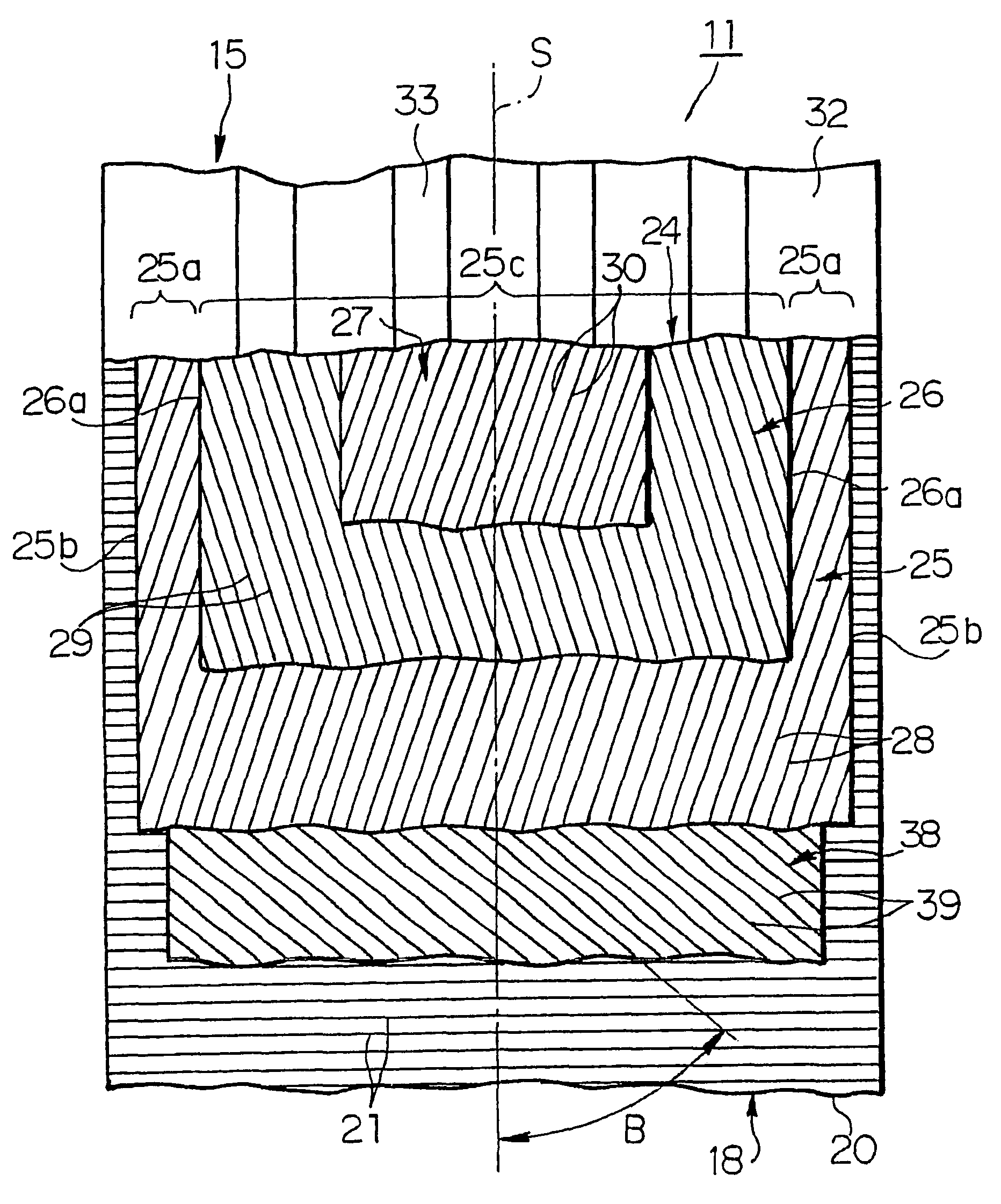
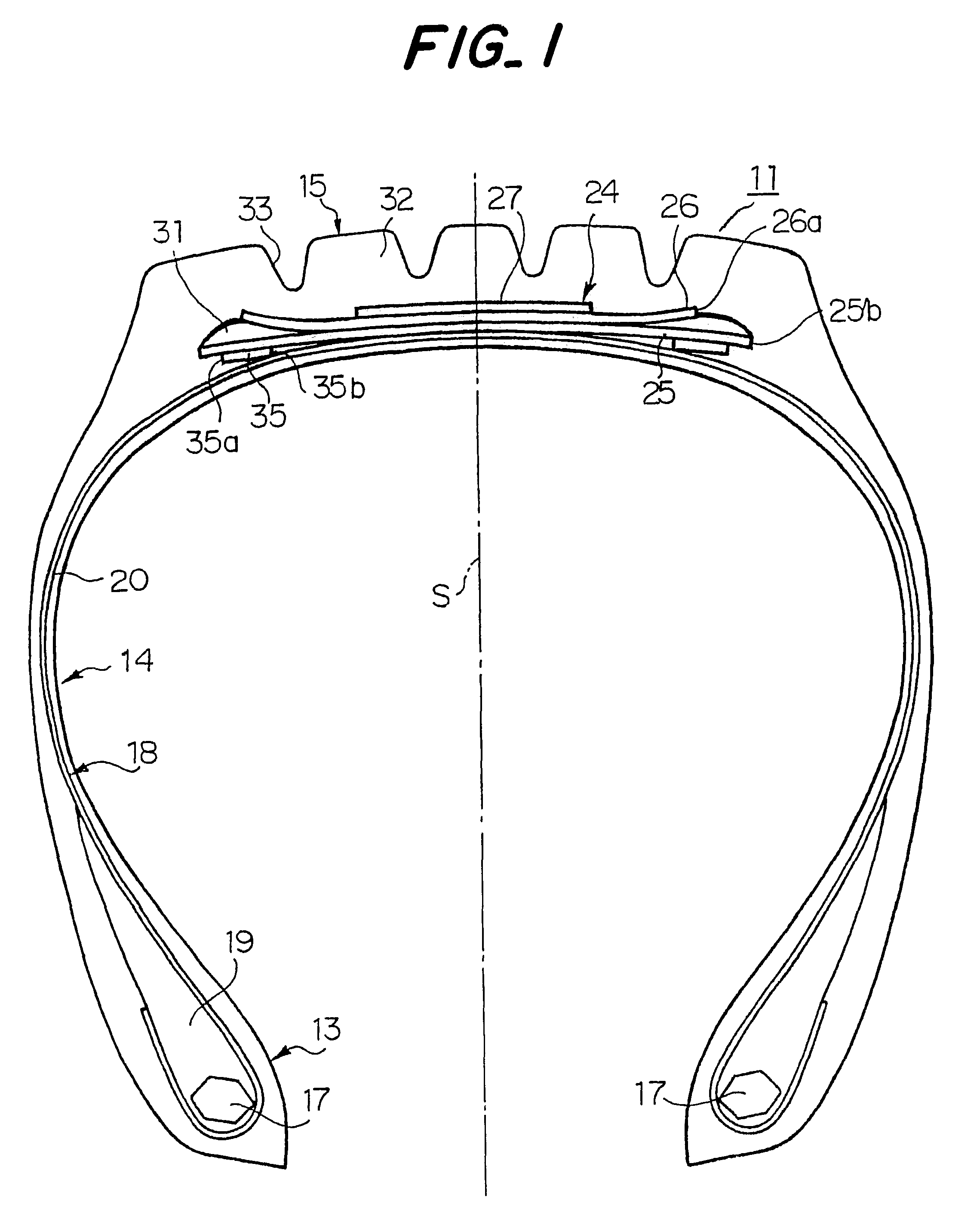
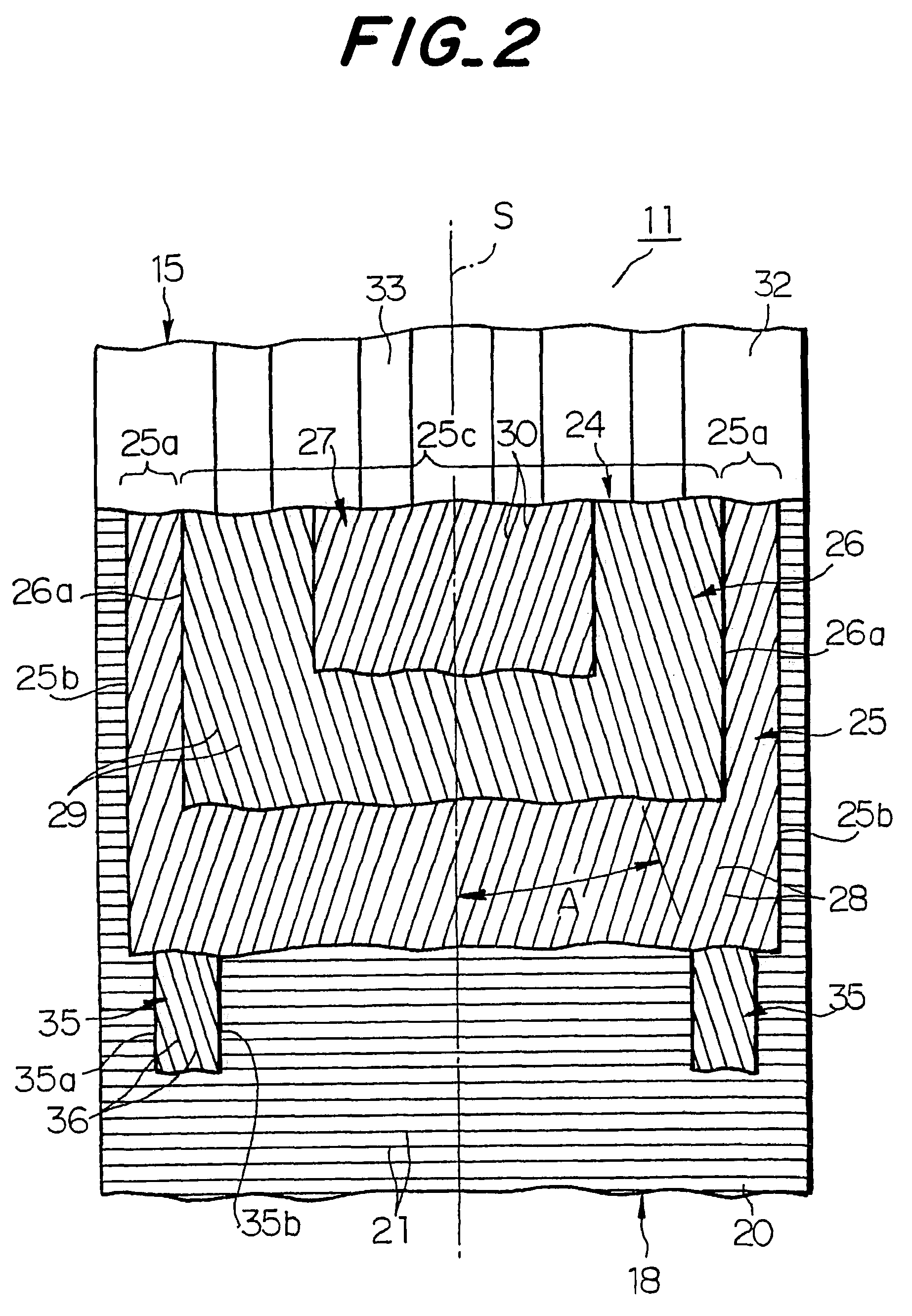
In FIGS. 1 and 2, numeral 11 is the heavy duty pneumatic radial tire for use in truck and bus according to the invention. The tire 11 comprises a pair of bead portions 13, a pair of sidewall portions 14 extending outward from these bead portions 13 in a radial direction of the tire, and a tread portion 15 of an approximately cylindrical form connecting radially outer ends of the sidewall portions 14 to each other. Further, the tire 11 comprises a carcass 18 toroidally extending between a pair of bead cores 17 embedded in the bead portions 13 and reinforcing the sidewall portions 14 and the tread portion 15. Each end portion of the carcass 18 is wound around the bead core 17 provided with a stiffener 19 from inside of the tire toward outside thereof. The carcass 18 is comprised of at least one rubberized carcass ply, one carcass ply 20 in this embodiment, which contains many inextensible cords 21 such as steel cords embedded therein and extending substantially in the radial direction...
second embodiment
the invention is described with reference to FIGS. 4 and 5. In this embodiment, a reinforcing layer 38 comprises a single layer continued in the widthwise direction by extending each of the reinforcing layers as in the first embodiment inward in the widthwise direction and integrally uniting them at the equatorial plane S in order to enhance the hoop effect of the belt 24 while simplifying the production. In this case, it is preferable that an inclination angle B of an inextensible cord 39 such as steel cord embedded in the reinforcing layer 38 is not less than 34.degree.. In this embodiment, the inclination angle B is 52.degree. upward to the left.
When the inclination angle B is less than 34.degree., a contracting quantity of a central portion 25c sandwiched between both widthwise outer end portions 25a in the widthwise direction is increased due to the influence of the reinforcing layer 38. Hence, the tensile strain in the widthwise direction of the widthwise outer end 26a of the ...
third embodiment
the invention is described with reference to FIGS. 7 and 8. In this embodiment, a reinforcing layer 44 is comprised of organic fiber cords 45 having a small stiffness instead of the inextensible cord such as steel cord. Since the organic fiber cord is low in the influence upon the cord 28 at the widthwise outer end portion 25a, if the reinforcing layer 44 is arranged at the inside of the maximum-width belt layer 25 in the radial direction, rubber located at the outside of the widthwise outer end portion 25a in the radial direction cannot sufficiently be displaced inward in the radial direction. Therefore, it is necessary that when the cord 45 is an organic fiber cord, the reinforcing layer 44 is arranged at the outside of the widthwise outer portion 25a in the radial direction to sandwich rubber located at the outside of the widthwise outer end portion 25a in the radial direction between the widthwise outer end portion 25a and the reinforcing layer 44. As a result the influence upon...
PUM
 Abstract
Description
Claims
Application Information
 - R&D
- Intellectual Property
- Life Sciences
- Materials
- Tech Scout
- Unparalleled Data Quality
- Higher Quality Content
- 60% Fewer Hallucinations
Browse by: Latest US Patents, China's latest patents, Technical Efficacy Thesaurus, Application Domain, Technology Topic, Popular Technical Reports.
© 2025 PatSnap. All rights reserved.Legal|Privacy policy|Modern Slavery Act Transparency Statement|Sitemap|About US| Contact US: help@patsnap.com


