Tissue remover and method

a tissue removal and tissue technology, applied in the field of medical devices, can solve the problems of ineffective use of nd:yag laser for in vivo tissue removal, inability to generate noxious and potentially toxic smoke, and inability to use the laser in some ways

Inactive Publication Date: 2003-12-30
BIOLASE TECH INC
View PDF3 Cites 378 Cited by
  • Summary
  • Abstract
  • Description
  • Claims
  • Application Information

AI Technical Summary

Problems solved by technology

Use of the Nd:YAG laser for in vivo tissue removal is in some ways inefficient, since the energy from the Nd:YAG laser is not highly absorbed by water.
Adjacent tissue can be charred or thermally damaged and, further, noxious and potentially toxic smoke can be

Method used


Image

  • Tissue remover and method
  • Tissue remover and method
  • Tissue remover and method

Examples


Embodiment Construction

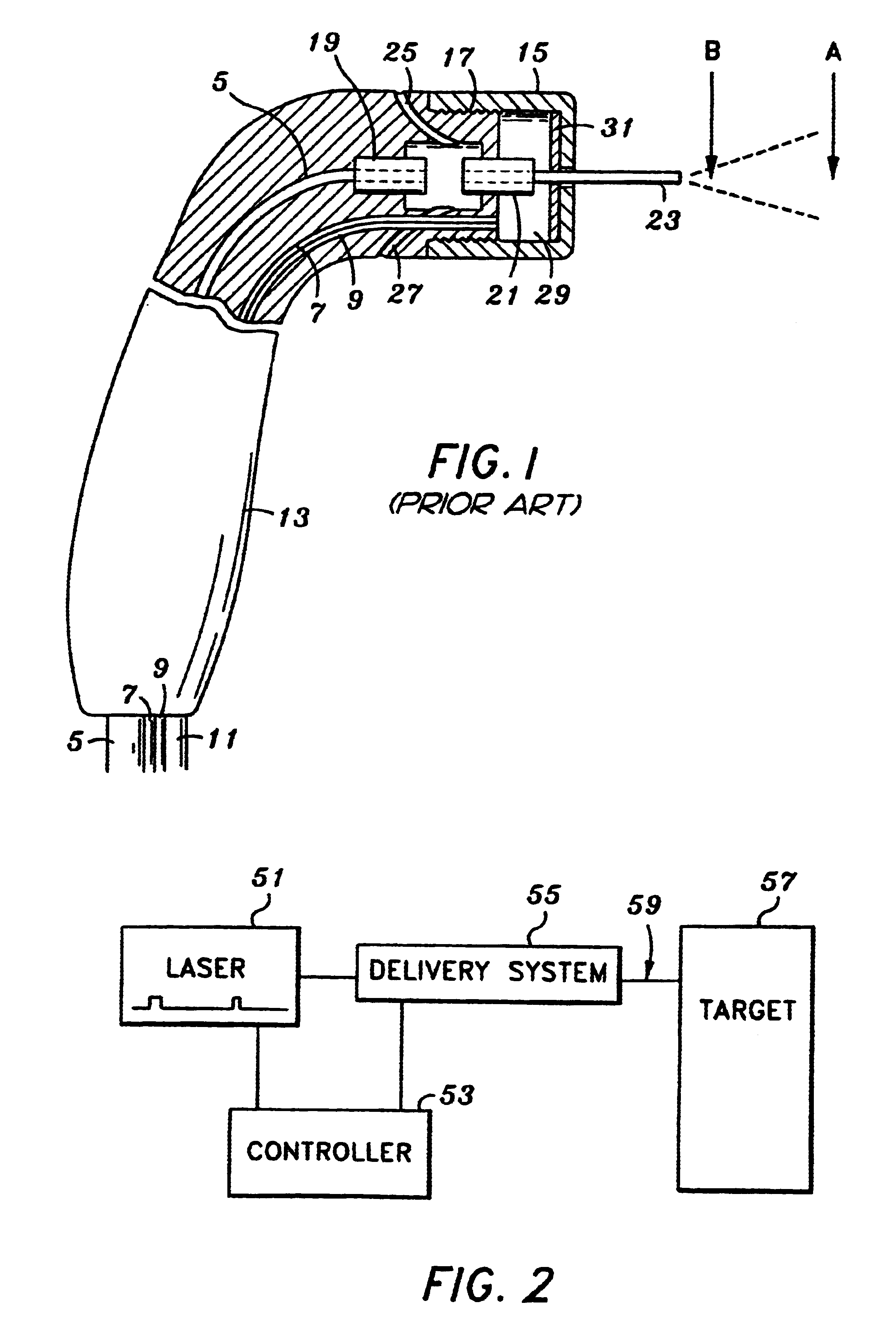
FIG. 2 is a block diagram illustrating an electromagnetically induced cutter in accordance with the present invention. An electromagnetic energy source 51 is coupled to both a controller 53 and a delivery system 55. The delivery system 55 imparts forces onto the target surface 57. As presently embodied, the delivery system 55 comprises a fiber optic guide for routing the laser 51 into an interaction zone 59, located above the target surface 57. The delivery system 55 further comprises an atomizer for delivering user-specified combinations of atomized fluid particles into the interaction zone 59. The controller 53 controls various operating parameters of the laser 51, and further controls specific characteristics of the user-specified combination of atomized fluid particles output from the delivery system 55.

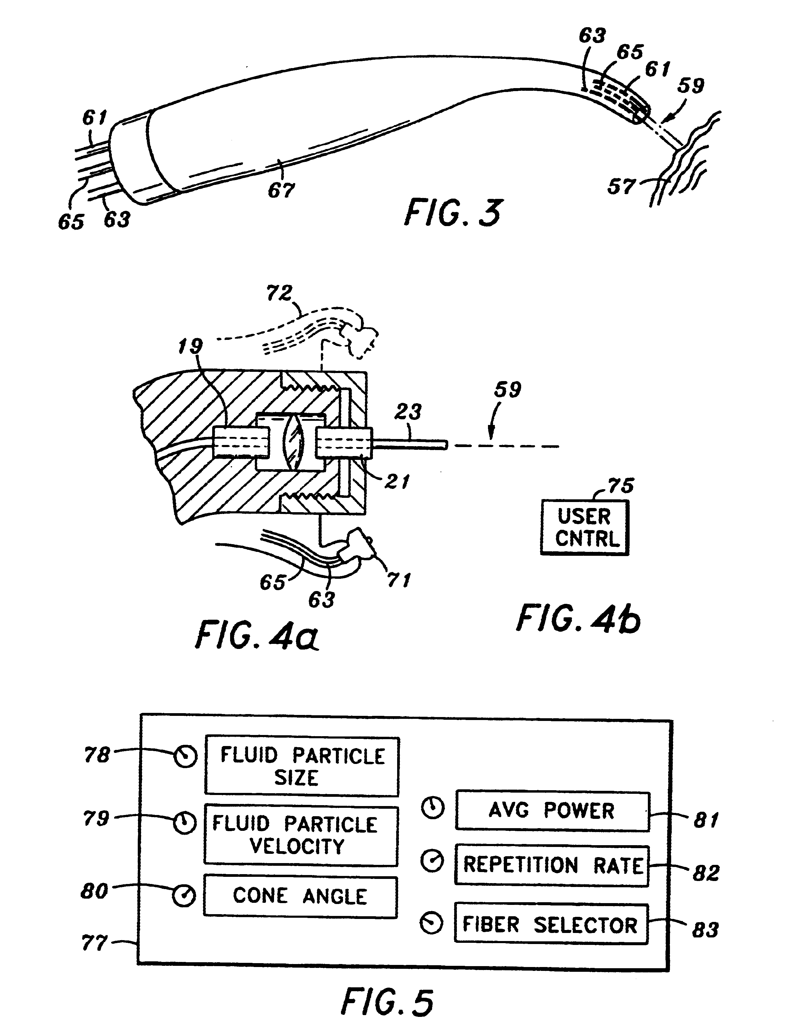
FIG. 3 shows a simple embodiment of the electromagnetically induced cutter of the present invention, in which a fiber optic guide 61, an air tube 63, and a water tube 65 are plac...


PUM

PropertyMeasurementUnit
Temperatureaaaaaaaaaa
Forceaaaaaaaaaa
Flow rateaaaaaaaaaa

Abstract

An electromagnetically induced cutting mechanism provides accurate cutting operations on soft tissues. The electromagnetically induced cutter is adapted to interact with atomized fluid particles. A tissue remover comprises an aspiration cannula housing a fluid and energy guide for conducting electromagnetically induced cutting forces to the site within a patient's body for aspiration of soft tissue. The cannula is provided with a cannula distal end. The proximal end of the cannula is provided with fluid flow connection to an aspiration source. Separated soft tissue and fluid are aspirated through the cannula distal end and the cannula by an aspiration source at the proximal end of the cannula.

Description

1. Field of the InventionThe present invention relates generally to medical apparatus and, more particularly, to methods and apparatus for cutting and removing soft or hard tissue by aspiration.2. Description of Related ArtTurning to FIG. 1, a prior art optical cutter includes a fiber guide tube 5, a water line 7, an air line 9, and an air knife line 11 for supplying pressurized air. A cap 15 fits onto the hand-held apparatus 13 and is secured via threads 17. The fiber guide tube 5 abuts within a cylindrical metal piece 19. Another cylindrical metal piece 21 is a part of the cap 15. The pressurized air from the air knife line 11 surrounds and cools the laser as the laser bridges the gap between the two metal cylindrical objects 19 and 21. Air from the air knife line 11 flows out of the two exhausts 25 and 27 after cooling the interface between elements 19 and 21.The laser energy exits from the fiber guide tube 23 and is applied to a target surface of the patient. Water from the wate...

Claims


Application Information

Patent Timeline
IPC IPC(8): A61B18/20B23K26/14A61B17/32A61B18/00A61M1/00B23K26/00
CPCA61B18/20B23K26/1417B23K26/0096A61B17/3203A61B2218/008B23K26/146
Inventor RIZOIU, IOANA M.KIMMEL, ANDREW I
Owner BIOLASE TECH INC
Why Eureka
Try Eureka