Al technical title is built by PatSnap Al team. It summarizes the technical point description of the patent document.
a technology of electromagnetic radiation and probes, applied in the field of electromagnetic radiation procedural devices, can solve the problems of ineffective prior art techniques, inadequate bacteria control, and causative agent in pulpal and periapical pathosis, and achieve the effect of accurate cutting operations
Inactive Publication Date: 2009-12-03
BIOLASE TECH INC
View PDF41 Cites 26 Cited by
Summary
Abstract
Description
Claims
Application Information
AI Technical Summary
This helps you quickly interpret patents by identifying the three key elements:
Problems solved by technology
Method used
Benefits of technology
[0016]The present invention discloses an electromagnetically induced cutting mechanism, which can provide accurate cutting operations on hard and soft tissues, and other materials as well. Soft tissues may include fat, skin, m
Problems solved by technology
A primary causative agent in pulpal and periapical pathosis is inadequate bacteria control.
While such instrumentation techniques of the prior art have not been altogether ineffective, they do tend to fall short of the goal of total or near total disinfection of the root canal system.
Here, too, infection of the root canal and adjacent dentin may persist, however, following such applications, owing perhaps to an inability of these agents to reach all the infecting microorganisms.
Regarding the third mentioned category, of medicaments, the use of intracanal medications, such as calcium hydroxide, has typically been ineffective in the context of short-term applications.
That is, longer term applications have frequently been indicated as a consequence, for example, of such agents failing to adequately address and eliminate endodontic infections by way of only a few applications.
Consequently,
Method used
Image
Click on the blue label to locate the original text in one second.
Reading with bidirectional positioning of images and text.
Examples
Embodiment Construction
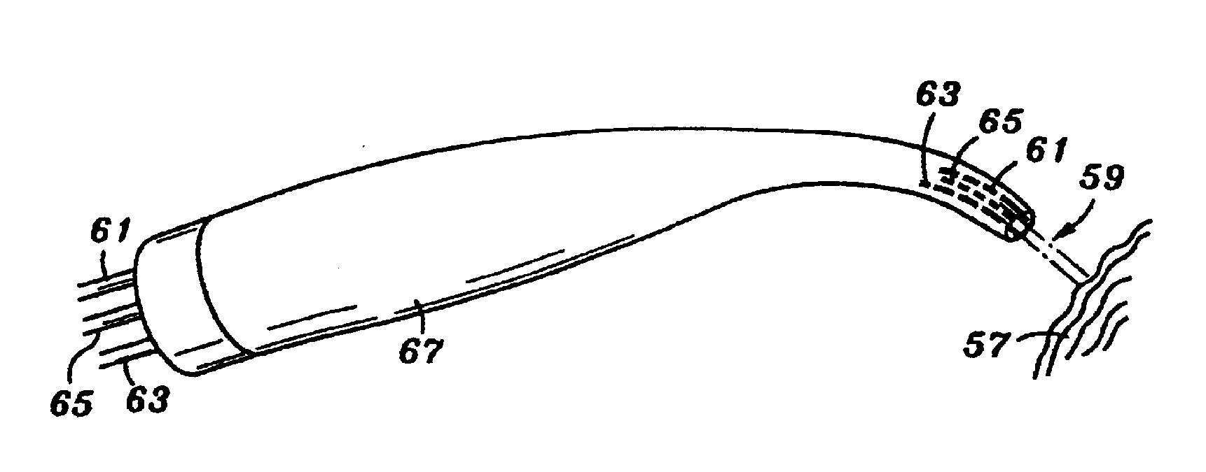
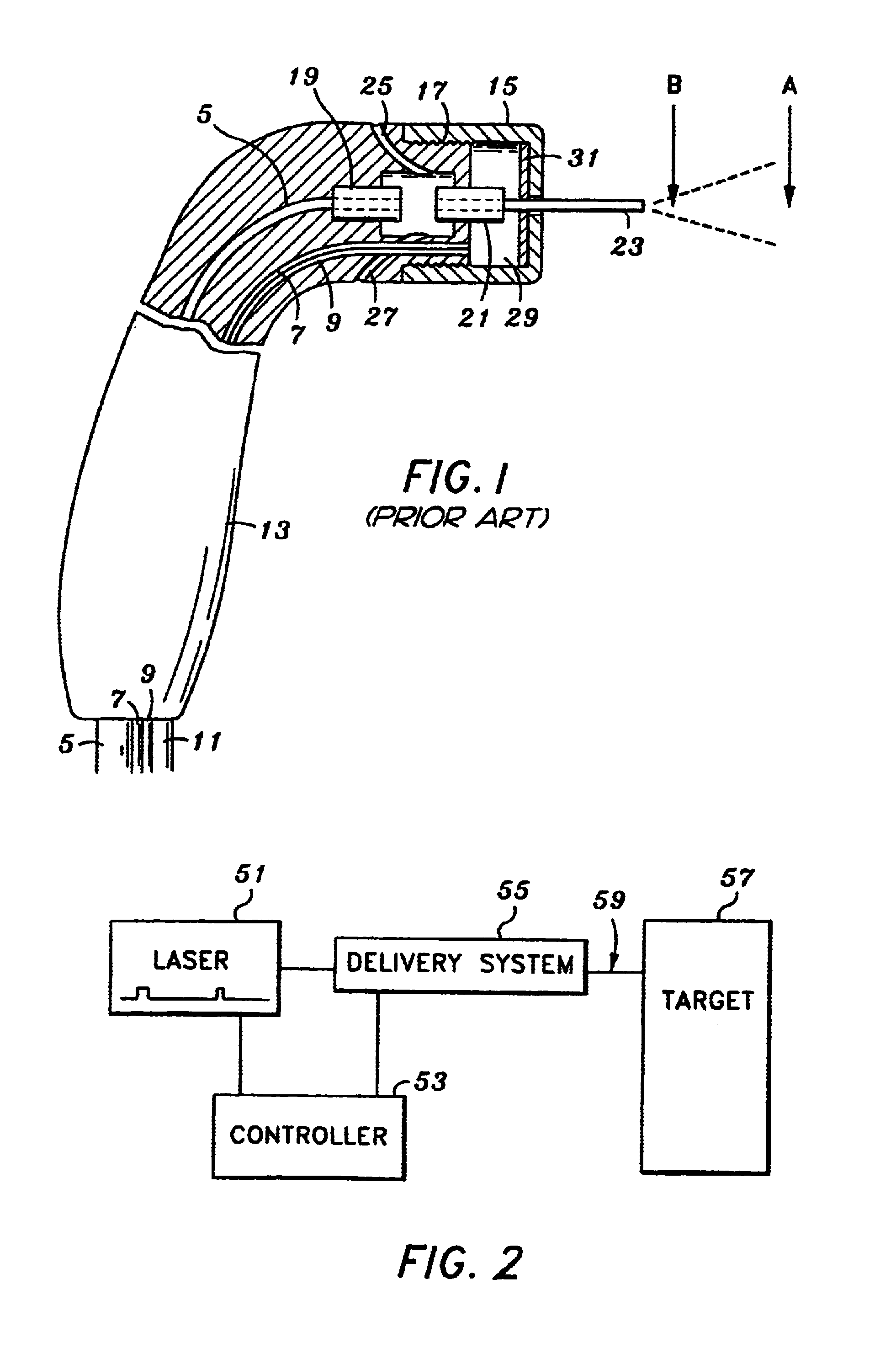
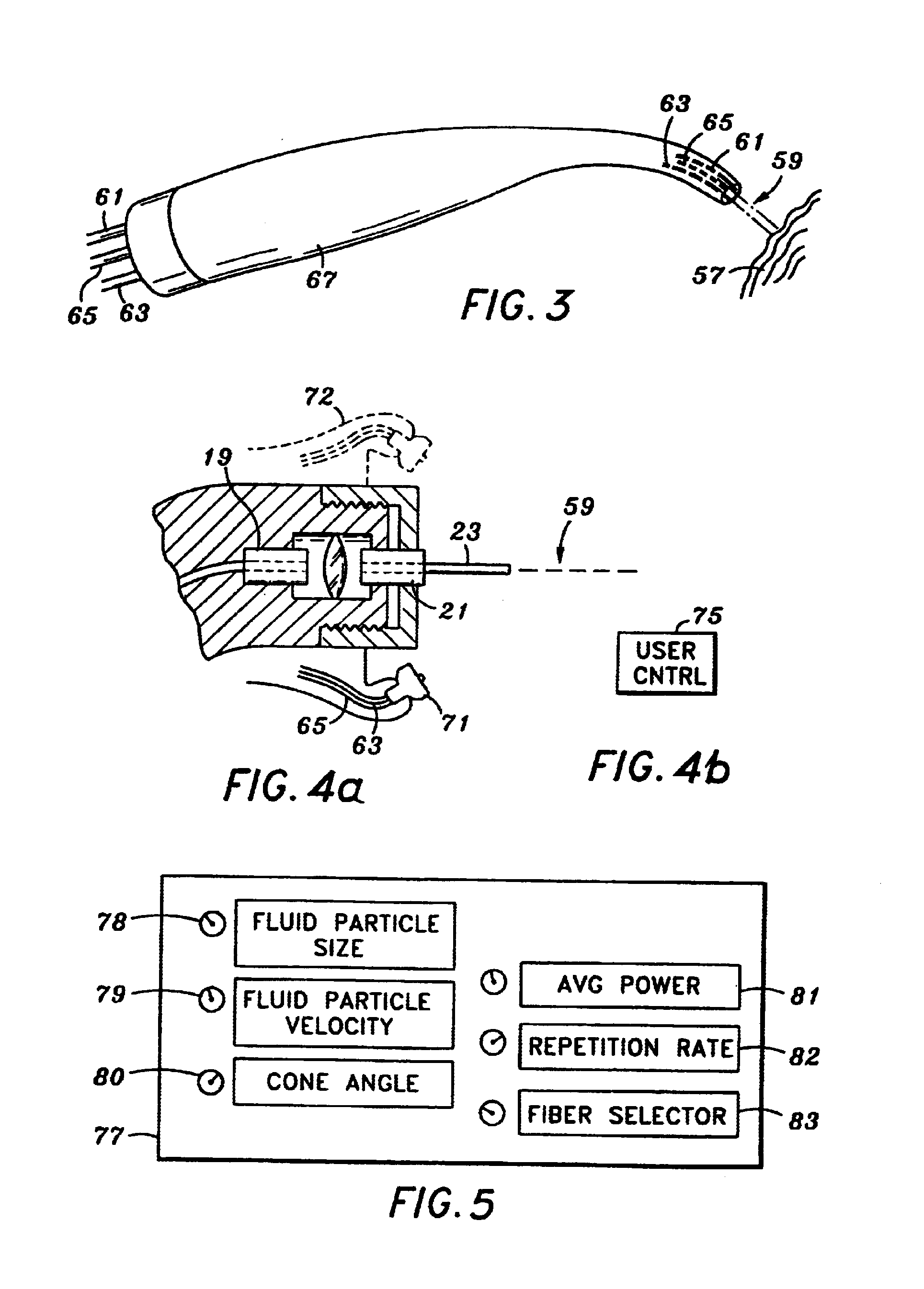
[0045]Reference will now be made to certain embodiments (e.g., certain illustrated embodiments) of the invention, examples of which are illustrated in the accompanying drawings. Wherever possible, the same or similar reference numbers are used in the drawings and the description to refer to the same or like parts. It should be noted that the drawings are in simplified form and are not presumed, automatically, to be to precise scale in all embodiments. That is, they are intended to be examples of implementations of various aspects of the present invention and, according to certain but not all embodiments, to be to-scale. While, according to certain implementations, the structures depicted in these figures are to be interpreted to be to scale, in other implementations the same structures should not. In certain aspects of the invention, use of the same reference designator numbers in the drawings and the following description is intended to refer to similar or analogous, but not necess...
PUM
Abstract
An electromagnetically induced cutting mechanism provides accurate cutting operations on soft tissues. The electromagnetically induced cutter is adapted to interact with atomized fluid particles. A tissue remover comprises an aspiration cannula housing a fluid and energy guide for conducting electromagnetically induced cutting forces to the site within a patient's body for aspiration of soft tissue. An endodontic probe is used to perform disinfection procedures on target tissues within root canal passages and tubules. The endodontic probe can include an electromagnetic radiation emitting fiber optic tip having a distal end and a radiation emitting region disposed proximally of the distal end. According to one aspect, the endodontic probe can include a porous structure that encompasses a region of the fiber optic tip excluding the radiation emitting region and that is loaded with biologically-active particles, cleaning particles, biologically-active agents, or cleaning agents for delivery from the porous structure onto the target tissues. Another aspect can include provision of the endodontic probe with an adjustable channel-depth indicator, which encompasses a region of the fiber optic tip besides the radiation emitting region and which is movable in proximal and distal directions along a surface of the fiber optic tip to facilitate the provision of depth-of-insertion information to users of the endodontic probe.
Description
PRIORITY INFORMATION[0001]This application claims the benefit of U.S. Provisional Application 61 / 046,394, filed Apr. 18, 2008. This application is a continuation-in-part of co-pending U.S. application Ser. No. 12 / 234,593, filed Sep. 19, 2008 and entitled PROBES AND BIOFLUIDS FOR TREATING AND REMOVING DEPOSITS FROM TISSUE SURFACES (Docket. BI8053P), which is commonly assigned and the contents of which are expressly incorporated herein by reference. U.S. application Ser. No. 12 / 234,593 claims the benefit of Prov. App. 60 / 995,759, filed on Sep. 28, 2007 (Docket BI8053PR), Prov. App. 60 / 994,891, filed on Sep. 21, 2007 (Docket BI8052PR), Prov. App. 60 / 994,723, filed on Sep. 20, 2007 (Docket BI8051PR), and Prov. App. 60 / 994,571, filed on Sep. 19, 2007 (Docket BI8050PR), the contents of all which are expressly incorporated herein by reference. This application is a continuation-in-part of co-pending U.S. application Ser. No. 10 / 667,921, filed Sep. 22, 2003 (Docket. BI9100CIPCON), which is ...
Claims
Application Information
Patent Timeline
Application Date:The date an application was filed.
Publication Date:The date a patent or application was officially published.
First Publication Date:The earliest publication date of a patent with the same application number.
Issue Date:Publication date of the patent grant document.
PCT Entry Date:The Entry date of PCT National Phase.
Estimated Expiry Date:The statutory expiry date of a patent right according to the Patent Law, and it is the longest term of protection that the patent right can achieve without the termination of the patent right due to other reasons(Term extension factor has been taken into account ).
Invalid Date:Actual expiry date is based on effective date or publication date of legal transaction data of invalid patent.