

Process for producing cyclic formal
a technology of cyclic formal and cyclic acid, which is applied in the field of process for producing cyclic formal, can solve the problems of inhibiting the production of impurities as by-products, troublesome and complicated purification steps following the reaction steps, and impurities in distillate liquids
- Summary
- Abstract
- Description
- Claims
- Application Information
AI Technical Summary
Benefits of technology
Problems solved by technology
Method used
Image

Examples
example 1
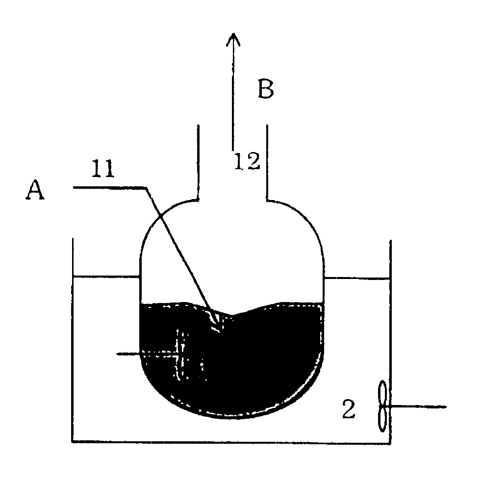
The apparatus shown in FIG. 1 was used. Thirty-five grams of ethylene glycol, 1.7 g of trioxane (amount of ethylene glycol (mole) / amount of trioxane in terms of formaldehyde (mole)=11.3), 8.3 g of 1,3-dioxolane, 45 g of pure water and 10 g of sulfuric acid were charged in a reaction vessel 1 of 300 ml, and were heated by an oil bath 2 so as to keep them at 105-115.degree. C. The pressure in the reaction vessel 1 was atmospheric pressure.
Then, a mixed liquid of ethylene glycol and trioxane (amount of ethylene glycol (mole) / amount of trioxane in terms of formaldehyde (mole)=0.65-0.75) was continuously fed to the reaction vessel 1. The mixed liquid was fed so that the liquid level in the reaction vessel 1 was kept constant.
The retention time was 1 hour, and the composition of inner liquid in the reaction vessel 1, composition of the distillate vapor, amount of the distillate vapor, etc. did not greatly change from those at the start of the reaction and were stable (amount of ethylene g...
example 2
The apparatus shown in FIG. 1 was used as in Example 1. Thirty-five grams of ethylene glycol, 5 g of trioxane (amount of ethylene glycol (mole) / amount of trioxane in terms of formaldehyde (mole)=3.4), 30 g of 1,3-dioxolane, 20 g of pure water and 10 g of sulfuric acid were charged in the reaction vessel 1 of 300 ml, and were heated by the oil bath 2 so that they were kept at 95-105.degree. C. The pressure in the reaction vessel 1 was 67 kPa.
Then, a mixed liquid of ethylene glycol and trioxane (amount of ethylene glycol (mole) / amount of trioxane in terms of formaldehyde (mole)=0.75-0.85) was continuously fed to the reaction vessel 1. The mixed liquid was fed so that the liquid level in the reaction vessel 1 was kept constant.
The retention time was 1 hour, and the composition of inner liquid in the reaction vessel 1, composition of the distilled vapor, amount of the distilled vapor, etc. did not greatly change from those at the start of the reaction and were stable (amount of ethylene...
example 3
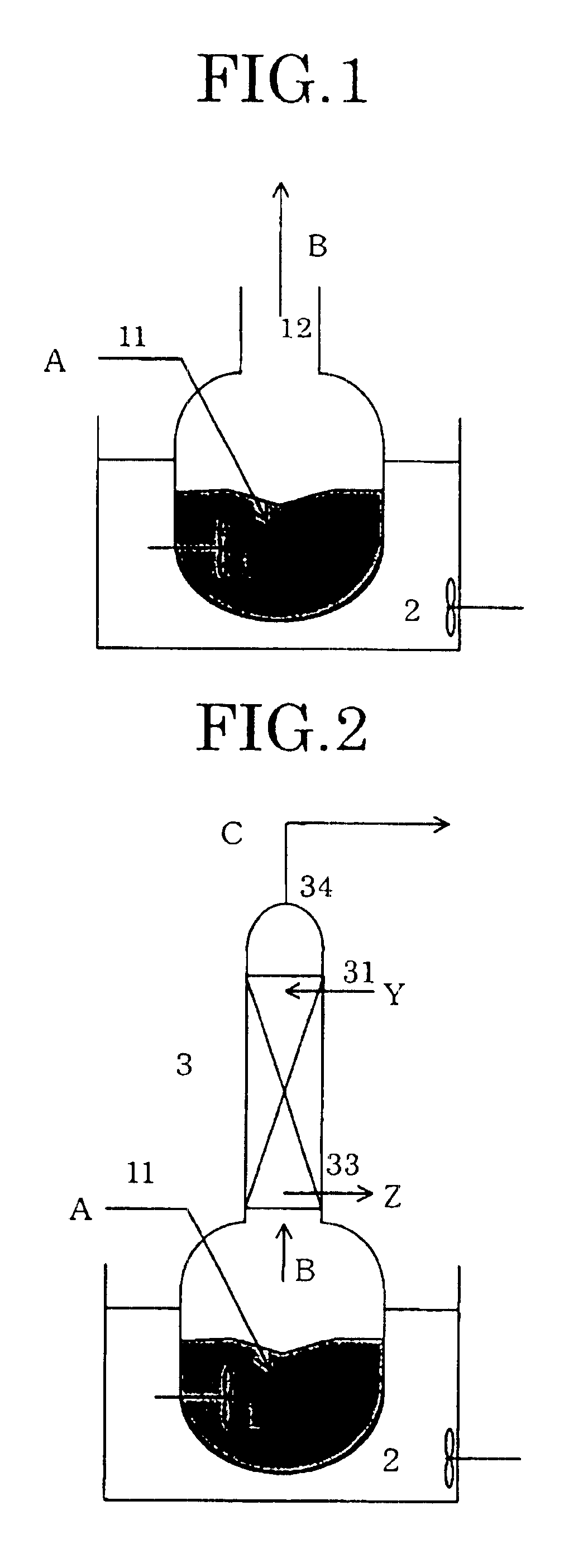
The apparatus shown in FIG. 2 was used. First, in the same manner as in Example 1, the reaction of ethylene glycol and trioxane was carried out in the reaction vessel 1.
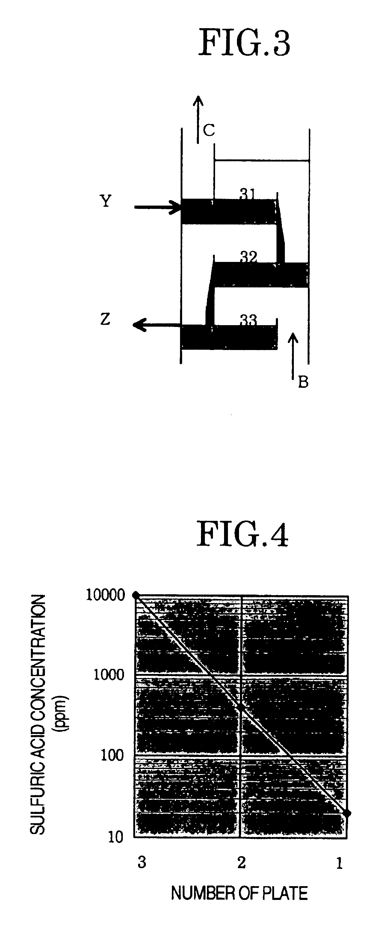
Then, the vapor B produced was supplied to the absorption tower 3 (number of plates: 5 plates) and was countercurrently contacted with the purified 1,3-dioxolane supplied from the uppermost plate 31 of the absorption tower 3. The vapor C after being subjected to the countercurrent contact was discharged from the top 34 of the absorption tower. The amount of the purified 1,3-dioxolane supplied was about 10% by weight based on the vapor C produced. The purified 1,3-dioxolane after the countercurrent contact was continuously drawn from the lowermost plate of the absorption tower 3.
As in Example 1, after a lapse of 10 hours from the start of the reaction, the resulting vapor C was condensed and the composition of this condensate was analyzed. The results are shown in Table 2. By additionally carrying out the countercurre...
PUM
| Property | Measurement | Unit |
|---|---|---|
| melting point | aaaaa | aaaaa |
| temperature | aaaaa | aaaaa |
| temperature | aaaaa | aaaaa |
Abstract
Description
Claims
Application Information