Efficient phase correction scheme for range migration algorithm

a phase correction and range migration technology, applied in the field ofradar signal processing systems, can solve the problems of smearing or duplication of target images, difficult to implement automatic focus functions during batch processing, and efficient phase correction

Inactive Publication Date: 2003-12-30
RAYTHEON CO
View PDF9 Cites 34 Cited by
  • Summary
  • Abstract
  • Description
  • Claims
  • Application Information

AI Technical Summary

Benefits of technology

Two alternative embodiments of the invention are described. The first embodiment adds padded zeros to the range compressed data in order to avoid the wrap around effect introduced by the FFT (Fast Fourier Transform). This embodiment requires a third step: the target dependent signal support needs to be shifted back to the initial position after phase correction. The second embodiment uses the range compressed data without padded zeros. Instead, an aperture of greater length needs to be generated by the Stolt interpolation. In this embodiment, the third step of shifting the signal support back can be eliminated.

Problems solved by technology

A difficulty with the RMA, however, is performing efficient phase correction.
Phase error introduced by the inaccuracy of navigation data or undesirable platform motion causes smearing or duplication of the target image.
However, for the case of RMA, it is difficult to implement the autofocus function during batch processing because the signal support areas from different targets are not aligned.
For this reason, the autofocus function had to be implemented before batch processing starts, at the cost of increased complexity and processing time.
Because of the difficulty in implementing the autofocus function during batch processing, current RMA systems perform the autofocus function during the pulse-to-pulse processing phase using a separate polar format processing algorithm.
This approach, however, has the disadvantage of implementation complexity and tighter processing timeline requirements.
Furthermore, the increased timeline requirement makes it more difficult, if not impossible, to implement more advanced autofocus techniques.

Method used


Image

  • Efficient phase correction scheme for range migration algorithm
  • Efficient phase correction scheme for range migration algorithm
  • Efficient phase correction scheme for range migration algorithm

Examples


Embodiment Construction

Illustrative embodiments and exemplary applications will now be described with reference to the accompanying drawings to disclose the advantageous teachings of the present invention.

While the present invention is described herein with reference to illustrative embodiments for particular applications, it should be understood that the invention is not limited thereto. Those having ordinary skill in the art and access to the teachings provided herein will recognize additional modifications, applications, and embodiments within the scope thereof and additional fields in which the present invention would be of significant utility.

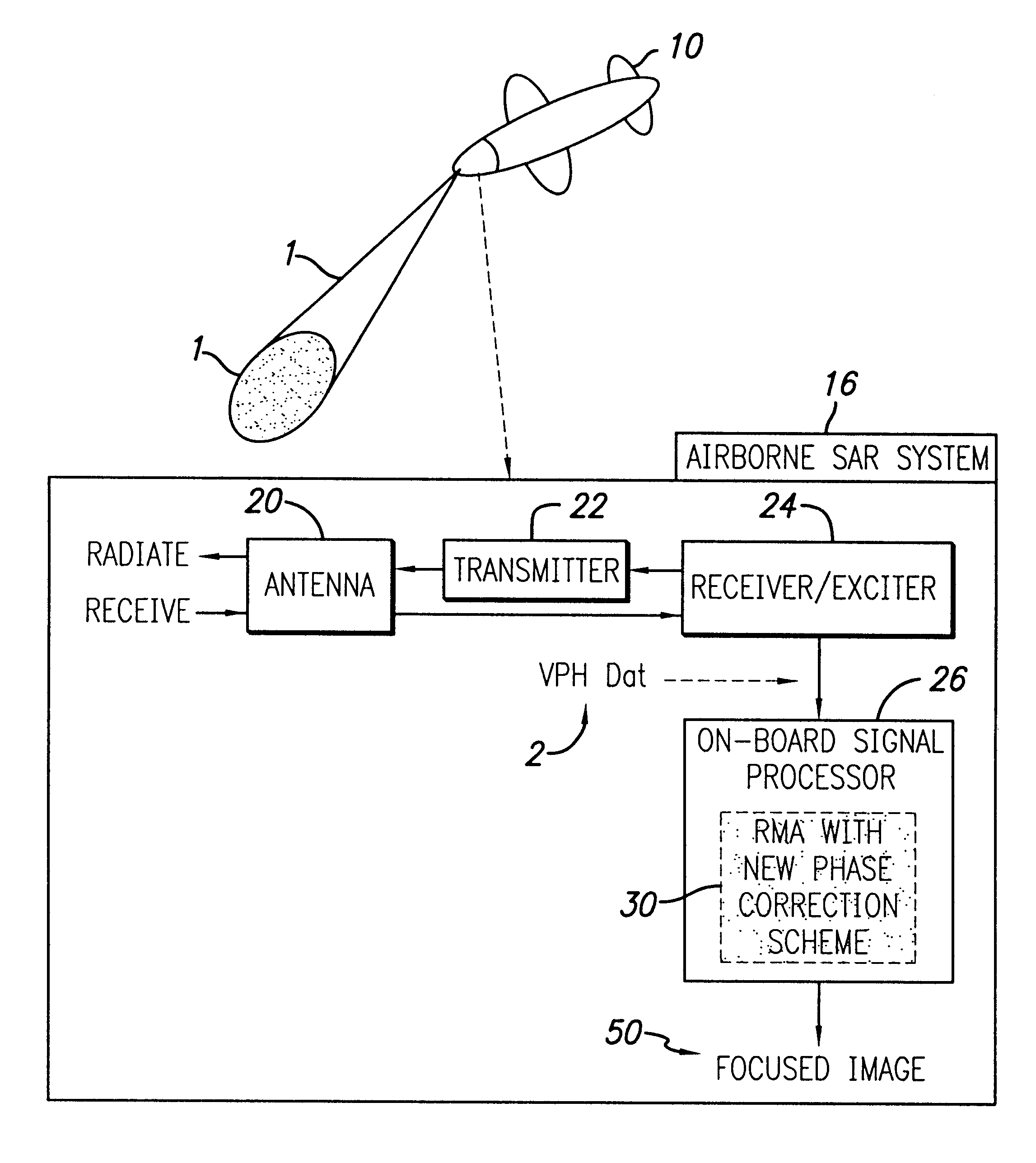
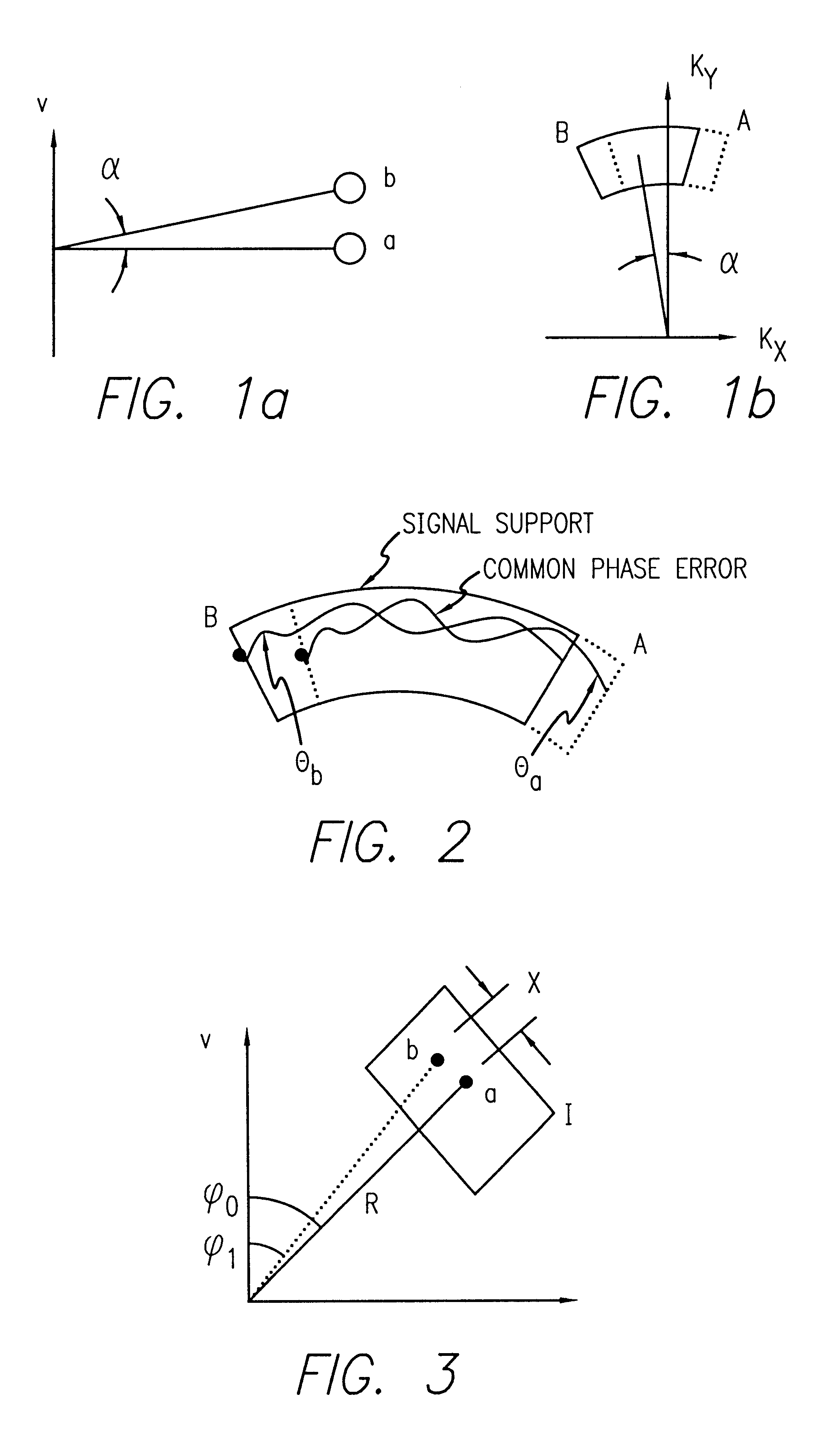
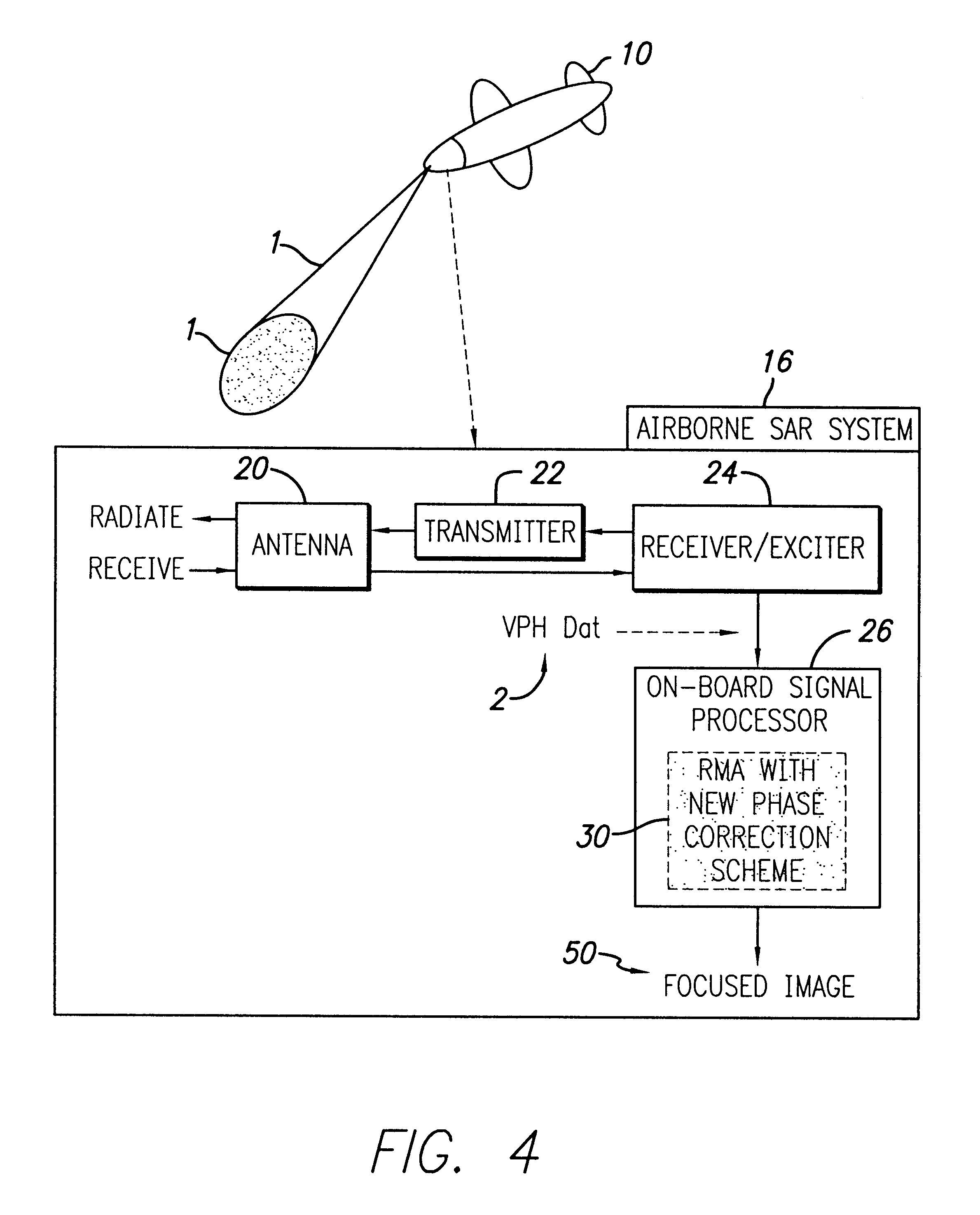
Considering the computational efficiency and simplicity, it is desirable to perform phase correction in synthetic aperture radar (SAR) systems during batch processing. It is difficult to implement autofocus techniques during batch processing in range migration algorithm (RMA) because the signal support areas in the spatial frequency domain from different targets...


PUM


Abstract

A system and method for efficient phase error correction in range migration algorithm (RMA) for synthetic aperture radar (SAR) systems implemented by making proper shifts for each position dependent phase history so that phase correction can readily be performed using the aligned phase history data during batch processing. In its simplest form, the invention (44) is comprised of two main parts. First (60), alignment of the phase error profile is achieved by proper phase adjustment in the spatial (or image) domain using a quadratic phase function. Second (62), the common phase error can be corrected using autofocus algorithms. Two alternative embodiments of the invention are described. The first embodiment (44a) adds padded zeros to the range compressed data in order to avoid the wrap around effect introduced by the FFT (Fast Fourier Transform). This embodiment requires a third step (64): the target dependent signal support needs to be shifted back to the initial position after phase correction. The second embodiment (44b) uses the range compressed data without padded zeros. Instead, an aperture of greater length needs to be generated by the Stolt interpolation. In this embodiment, the third step (64) of shifting the signal support back can be eliminated.

Description

1. Field of the InventionThe present invention relates to radar signal processing systems. More specifically, the present invention relates to phase error correction in range migration algorithm (RMA) for synthetic aperture radar (SAR) systems.2. Description of the Related ArtIn imaging applications such as ground mapping, a radar system is used to generate a two-dimensional image of a portion of a ground surface in the range and azimuth (cross-range) directions. A large antenna aperture is required in conventional imaging radar systems in order to achieve a narrow beamwidth and, consequently, fine azimuth resolution. Synthetic aperture radar (SAR) systems have been developed as an alternative means for improving azimuth resolution by synthesizing pulse-to-pulse return signals collected by a moving platform with a small antenna. The signal synthesis from many successive locations of the moving platform accomplishes what would otherwise require a larger antenna aperture.Polar format ...

Claims


Application Information

Patent Timeline
Patent Type & Authority Patents(United States)
IPC IPC(8): G01S13/90G01S13/00G01S7/40
CPCG01S7/4021G01S13/9035G01S2013/9041G01S13/9011G01S13/9019G01S13/904G01S13/9041
Inventor CHO, KWANG M.
Owner RAYTHEON CO
Why Eureka
Try Eureka