
Two-thread lock-stitch sewing machine with thread cutter

a technology of thread cutter and sewing machine, which is applied in the direction of needle severing device, sewing apparatus, textiles and paper, etc., can solve the problems of increased manufacturing cost, increased manufacturing cost, and increased manufacturing cost, and achieves the effect of reducing the manufacturing cost of the thread cutter and ensuring the safety of operation

Inactive Publication Date: 2004-01-06
DURKOPP ADLER AG
View PDF4 Cites 5 Cited by
  • Summary
  • Abstract
  • Description
  • Claims
  • Application Information

AI Technical Summary

Benefits of technology

The invention is a two-thread lock-stitch sewing machine with a thread cutter. The machine has a bearing plate for a workpiece and a stitch hole for a sewing needle to pass through. A shuttle with a thread pulling knife is movable between a swung-out position and a swung-in position. The machine also has cams and a hook that seizes the threads and cuts them. The thread cutter has a hook that seizes the threads and a cutting edge that performs a cutting motion in an x-y plane that extends at right angles to the vertical axis of rotation of the shuttle. The invention aims to provide a durable and reliable mode of operation with a decrease in manufacturing costs of the thread cutter.

Problems solved by technology

The fact that the thread puller and the cutting knife are formed on the ends of sectors of an annulus demands for a complicated bearing arrangement.
All this leads to an overall construction that is accompanied with a considerable manufacturing cost and consists of a considerable number of components, by which to achieve a mode of operation of only limited durability and reliability.
The effect of this cost advantage is even stronger when the bearing plate is provided with a stitch hole and thus subject to special wear.
Furthermore, integrating two components leads to reduced manufacturing costs and simplified handling during maintenance and repair.

Method used


Image

  • Two-thread lock-stitch sewing machine with thread cutter
  • Two-thread lock-stitch sewing machine with thread cutter
  • Two-thread lock-stitch sewing machine with thread cutter

Examples


Embodiment Construction

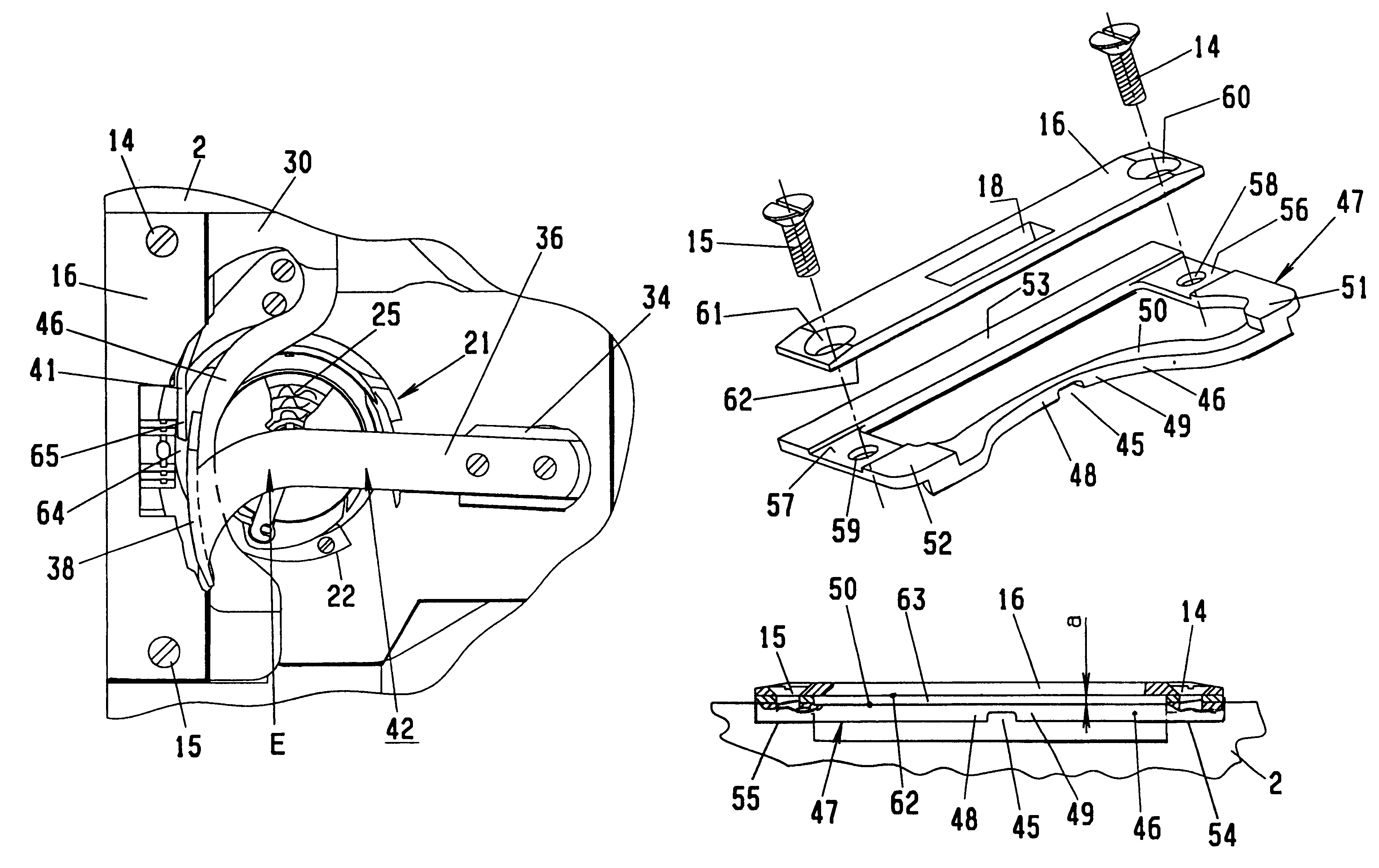
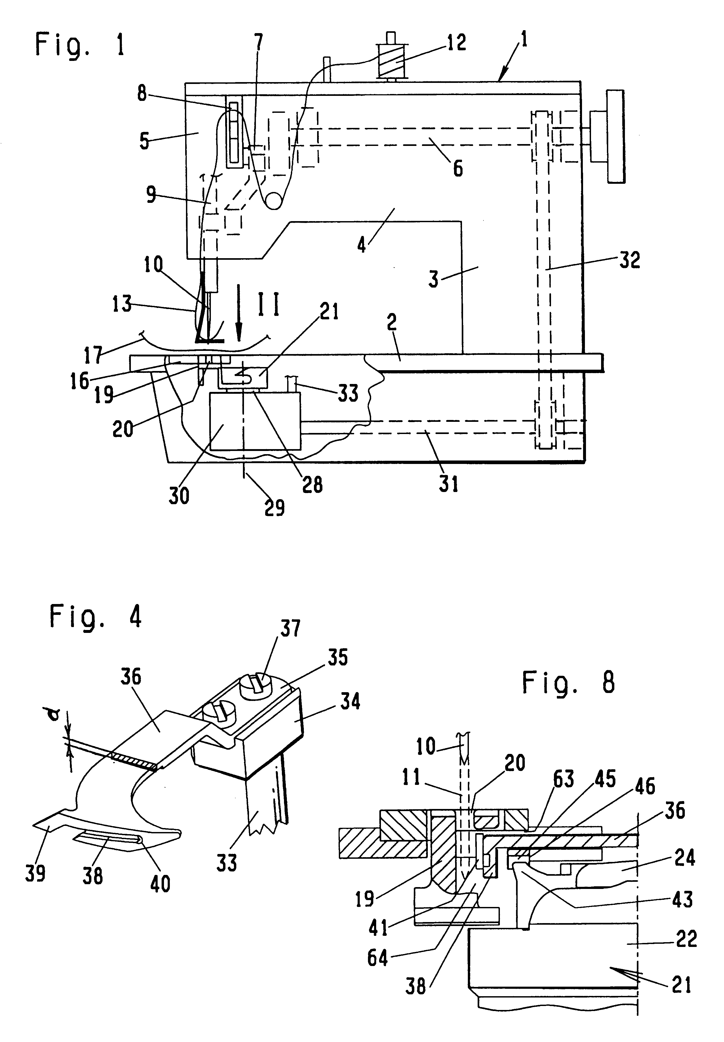
A sewing machine 1 comprises a base plate 2 with a standard 3 extending upwards therefrom and an elbowed arm 4 which terminates in a head 5. An arm shaft 6 is rotatably lodged in the arm 4, actuating, in the head 5, a crank drive 7 with a thread lever 8. The crank drive 7 is in driving connection with a needle bar 9 which is housed for displacement in the head 5, having a sewing needle 10 at its lower end. Consequently, the sewing needle 10 is movable by the crank drive 7 to reciprocate up and down, with the sewing needle 10 passing through a motion travel 11. In an eye, the sewing needle 10 carries a thread which is supplied from a bobbin 12 via a thread tightener and the thread lever 8 and which is designated hereinafter as the needle thread 13.

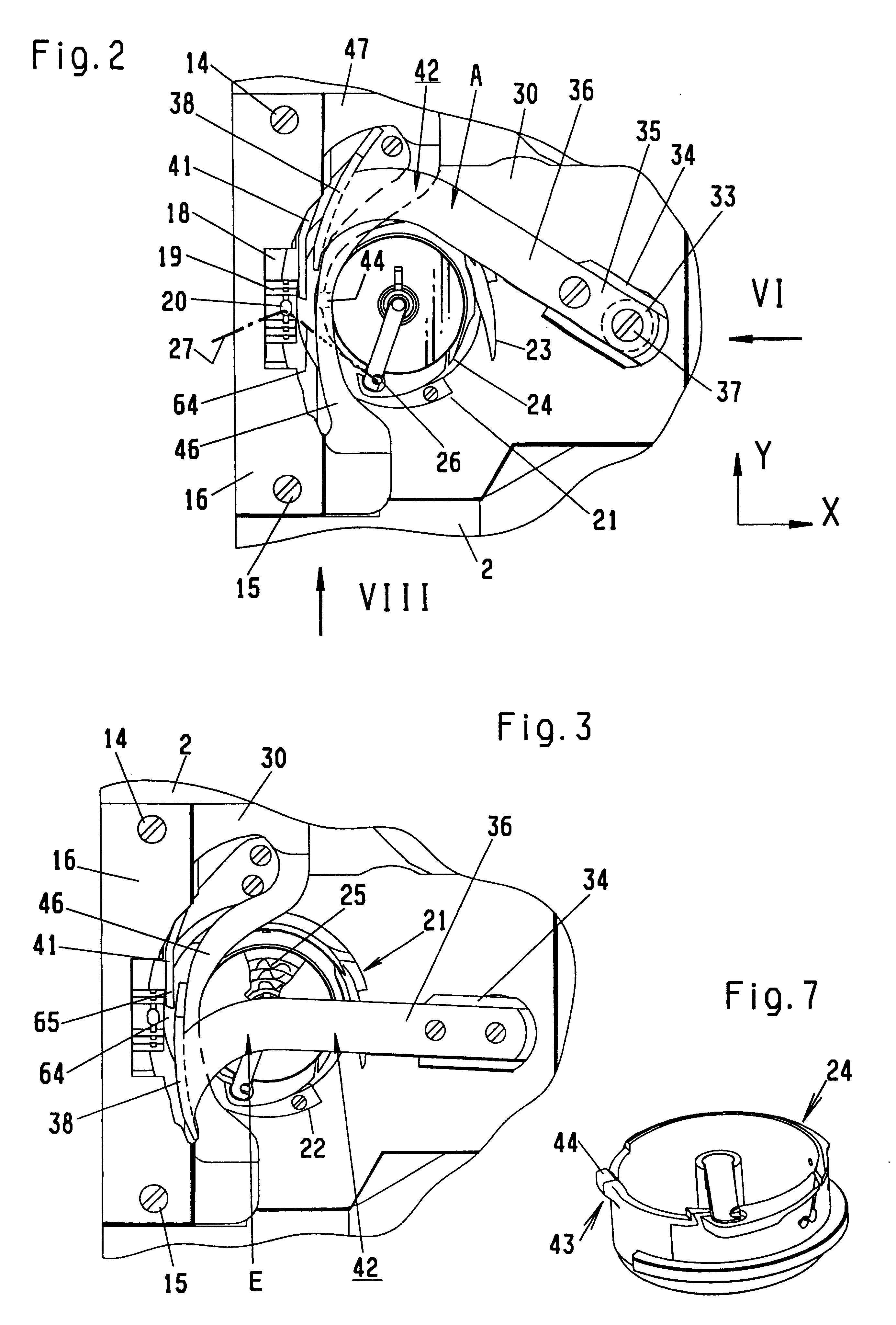
Positioned on the base plate 2 is a bearing plate 16 which is fastened by screws 14, 15 and has a workpiece 17 resting on it. The bearing plate 16 is equipped with a recess 18 for a feeder 19 to reach through. The feeder 19 has a stitch hol...


PUM


Abstract

A two-thread lock-stitch sewing machine with a thread cutter comprises a shaft which is parallel to the vertical axis of a shuttle and has a lever arm with a thread pulling knife disposed on it. The bobbin case in the shuttle has a holding finger which is directed toward a stitch hole and is held between two cams that are arranged on a rib. Formed between the cams and the workpiece bearing plate is an interspace which the lever arm passes through, together with the thread pulling knife projecting into a space between the motion travel of the sewing needle and the cams so that a thread cutting operation is enabled to be performed with very short thread tail pieces remaining on the lower side of the workpiece. The thread cutting operation excels by simple design and reliable operation.

Description

1. Field of the InventionThe invention relates to a two-thread lock-stitch sewing machine with a thread cutter, comprising the following features: a bearing plate for a workpiece; a stitch hole formed in the bearing plate or in the feeder for a sewing needle to pass through that carries a needle thread and reciprocates up and down along a motion travel; a bearing block is arranged underneath the bearing plate, having a shuttle rotatably lodged in it; the shuttle has a shuttle body that rotates about a vertical axis with a bobbin case rotatably accommodated therein inclusive of shuttle thread supplies; two stationary cams which are disposed in proximity to the stitch hole and a holding finger which is provided on the bobbin case and has an end located between the cams; the thread cutter with a thread pulling knife, which is movable to reciprocate between a swung-out position and a swung-in position, performing a cutting motion in an x-y plane that extends at right angles to the axis,...

Claims


Application Information

Patent Timeline
Patent Type & Authority Patents(United States)
IPC IPC(8): D05B65/00D05B57/10D05B57/00D05B73/12D05B73/00D05B65/02D05B65/06
CPCD05B65/00D05B57/143D05B73/12
Inventor ENNS, JOHANNRIFFEL, ANDREAS
Owner DURKOPP ADLER AG
Learn More