
Iterative rake receiver and corresponding reception process

a technology of rake receiver and receiver, which is applied in the field of iterative rake receiver and corresponding reception process, can solve the problems of severe loss of transmission quality, loss of performance, and reduction of global quality of channel estimate,

Inactive Publication Date: 2004-01-06
FRANCE TELECOM SA
View PDF11 Cites 28 Cited by
  • Summary
  • Abstract
  • Description
  • Claims
  • Application Information

AI Technical Summary

Problems solved by technology

For a given received power, this increase in the number of paths tends to reduce the power received per path and therefore to reduce the global quality of the channel estimate.
Consequently, a constructive combination of contributions from these paths to the receiver is rarely guaranteed and can result in a severe loss of transmission quality.
Since CDMA systems are inherently limited by multiple access interference, this loss of performance cannot be compensated by increasing the power.
Furthermore, a solution involving an increase in the number of pilot symbols would reduce the system capacity.

Method used


Image

  • Iterative rake receiver and corresponding reception process
  • Iterative rake receiver and corresponding reception process
  • Iterative rake receiver and corresponding reception process

Examples


Embodiment Construction

The following mathematical developments, like the figures, are applicable to the case in which symbols are multiplexed in time only, for simplification and notation reasons. The case in which the symbols are multiplexed in time and by code on components in quadrature is dealt with in a similar manner.

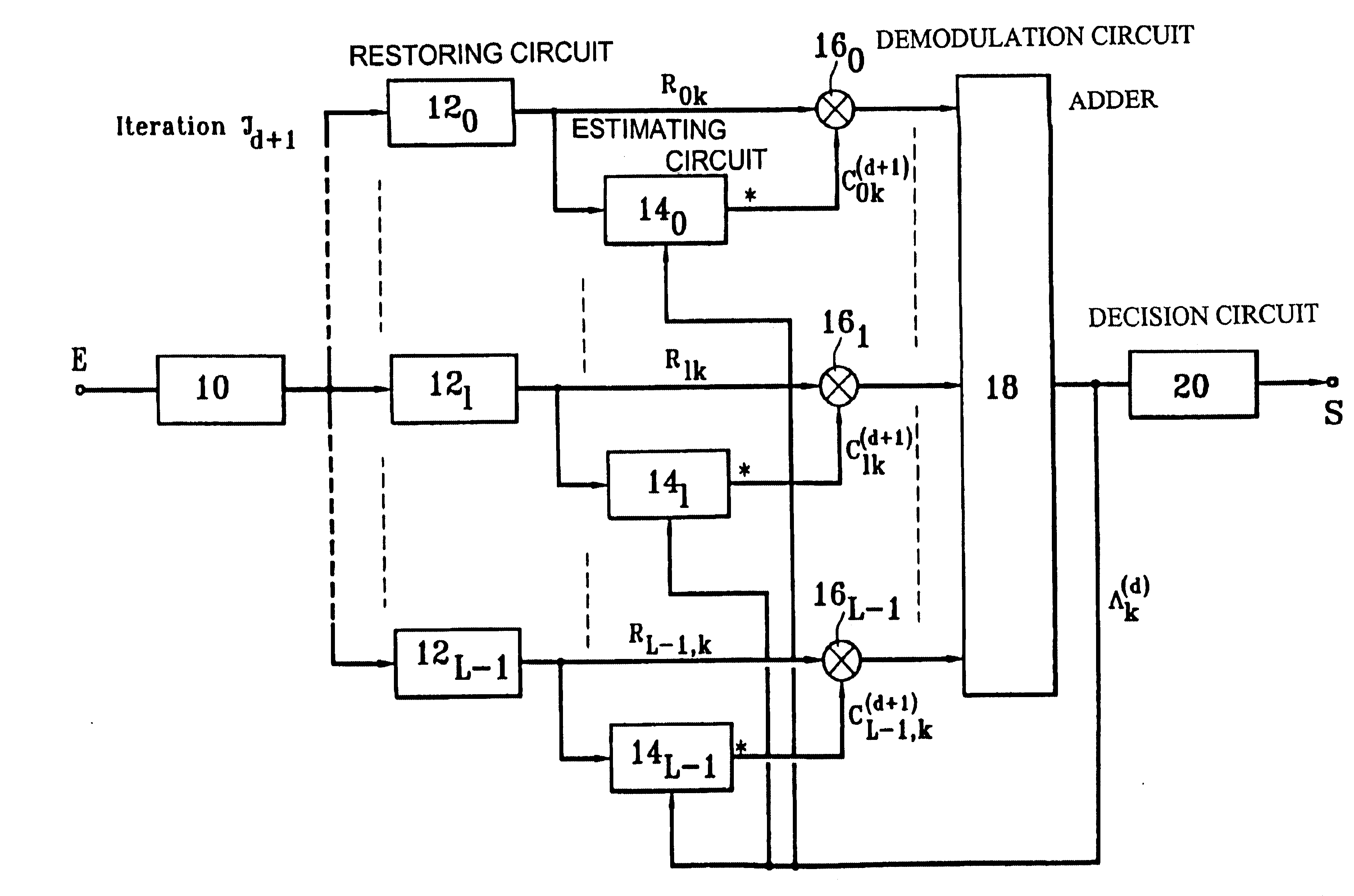
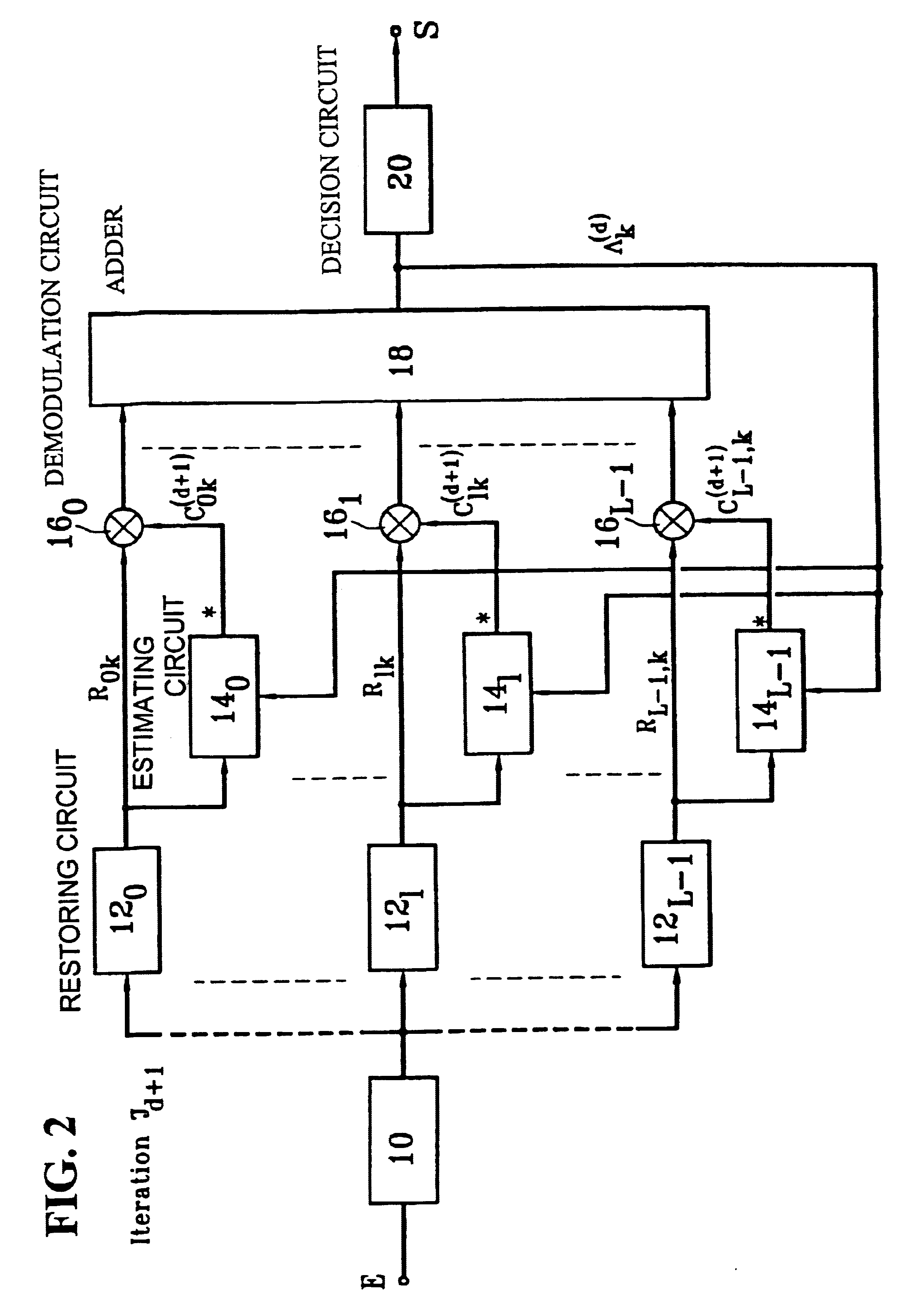
The receiver according to the invention searches for a representation of the multipath channel according to a criterion called the maximum a posteriori (MAP) probability criterion. This estimate requires knowledge of the emitted symbols, or at least their probability. In one particular embodiment, the receiver may use estimates present at the adder output. Therefore in this case, the output is looped back onto the various estimators as shown in FIG. 2. This figure shows that the output from the adder 18, that outputs a signal denoted .LAMBDA..sub.k (where k denotes the rank of the symbol being processed, this rank varying from 0 to N-1 as explained later) is looped back on estimators 14...


PUM


Abstract

A CDMA radiocommunication signals receiver for receiving signals obtained from spectrum symbols spread using pseudo-random sequences and having been propagated along a number of paths. The receiver includes a filter configured to restore L unspread signals for each symbol, corresponding to L different paths, a calculating circuit configured to calculate L estimates of the L different paths, and a demodulator configured to process each of the L unspread signals using the corresponding L estimates to obtain L path contributions. Also included is an adder configured to form a sum of the L path contributions and for outputting an estimate of a received symbol, and a decision circuit configured to make a decision about a value of the received symbol based on a value of the estimate of the received symbol output by the adder. Further, the receiver processes blocks of N symbols, each block having data symbols and control symbols, each symbol being identified by a rank k that it occupies in the block, where k varies from 0 to N-1. Also, for each path identified by an index l, where l varies from 0 to L-1, and for each block, the receiver considers a vector Cl with N components that characterizes the path during the block, and the receiver defines a vector base BK, vectors of the vector base BK being N eigenvectors of the matrix E [ClCl<.T>], each vector Cl being decomposed in the vector base, where decomposition coefficients denoted GlK form independent random Gaussian variables. In addition, coefficients GlK, define a vector Gl with N components for each path l, and the calculating circuit estimates each vector Gl, using an iterative process based on EM estimation-maximization algorithm based on a maximum a posteriori probability criterion.

Description

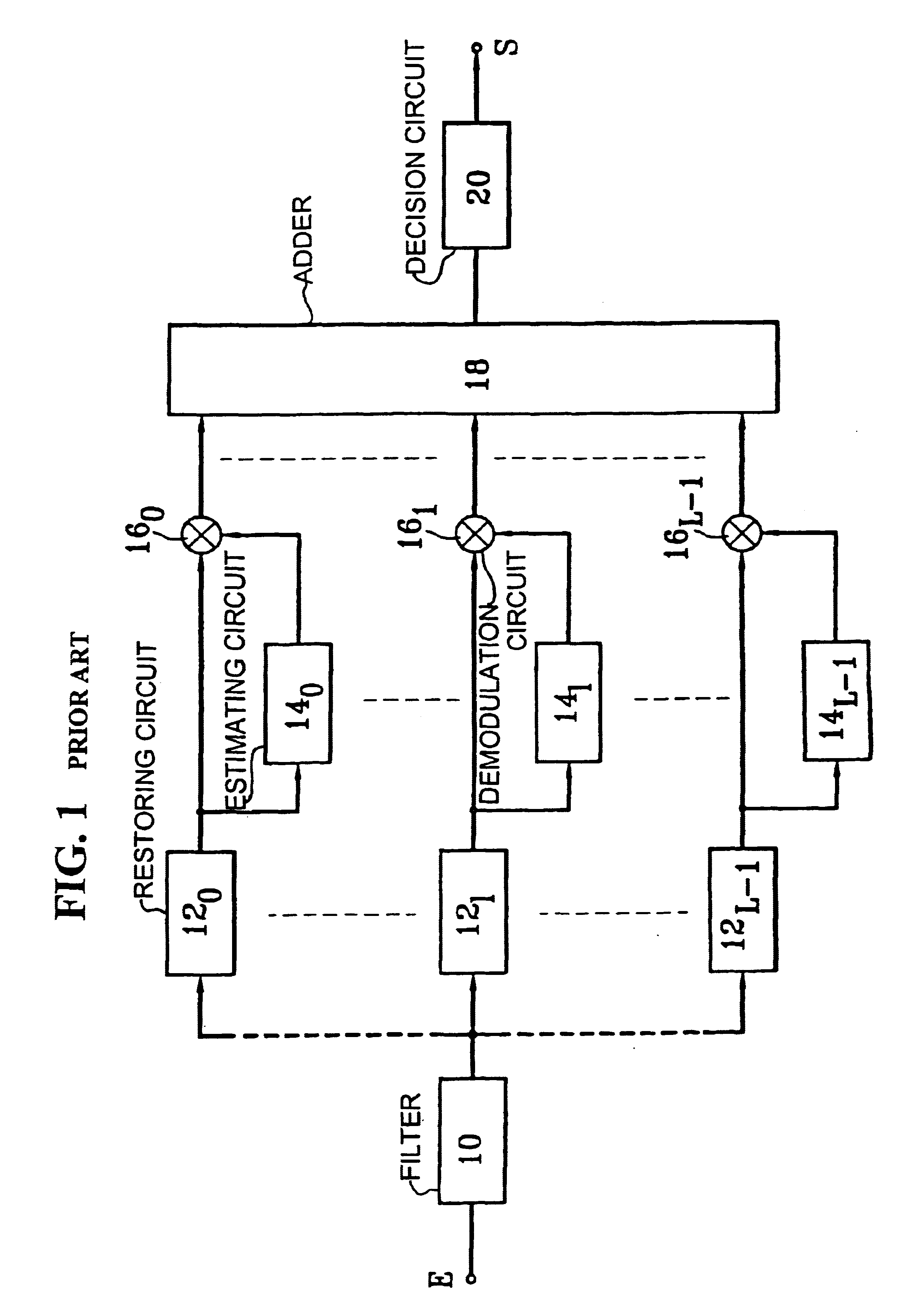
1. Field of the InventionThe purpose of this invention is an iterative rake receiver and a corresponding reception process. It is used in radiocommunications applications and more particularly in the Code Division Multiple Access (CDMA) technique. It may be applied to the system defined by the IS'95 standard and in third generation UMTS and IMT-2000 systems.2. Discussion of the BackgroundIn the CDMA technique, information symbols that are to be transmitted do not directly modulate a carrier, but are firstly multiplied by pseudo-random sequences (or codes) which have the effect of spreading their spectrum. On reception, the received signal is unspread by filtering adapted to the sequence used in transmission (or by correlation) and is then demodulated.This technique enables several users to use the same radiocommunications channel, provided that a particular sequence is assigned to each.A multipath channel is generally used, in the sense that the radio-electric wave propagates along ...

Claims


Application Information

Patent Timeline
IPC IPC(8): H04B7/204H04B1/16H04B7/216H04B1/707H04Q7/38H04B1/711H04J13/00H04W88/02
CPCH04B1/711H04J13/0022
Inventor SIALA, MOHAMED
Owner FRANCE TELECOM SA
Learn More