Method and system for controlling splice attenuation

a technology of attenuation and splicing, applied in the field of fiber optics, can solve the problems of laborious operation, inability to accurately determine the attenuation value of conventional techniques, and difficulty in controlling the amount of attenuation

Inactive Publication Date: 2004-01-13
CIENA
View PDF6 Cites 43 Cited by
  • Summary
  • Abstract
  • Description
  • Claims
  • Application Information

AI Technical Summary

Problems solved by technology

Furthermore, these operations are labor intensive and include typing in the large number of parameters at each step.
Even with an experienced operator and ideal conditions, these conventional techniques cannot provide an accurate attenuation value.
A major shortcoming of such techniques is the amount of attenuation is very difficult to control.
This technique has serious shortcomings and can only produce at attenuation of greater than 10 dB.

Method used


Image

  • Method and system for controlling splice attenuation
  • Method and system for controlling splice attenuation
  • Method and system for controlling splice attenuation

Examples


first embodiment

The operation of the invention will now be described in reference to FIGS. 2-8. Further embodiments will be described in relation to FIGS. 9-18 below.

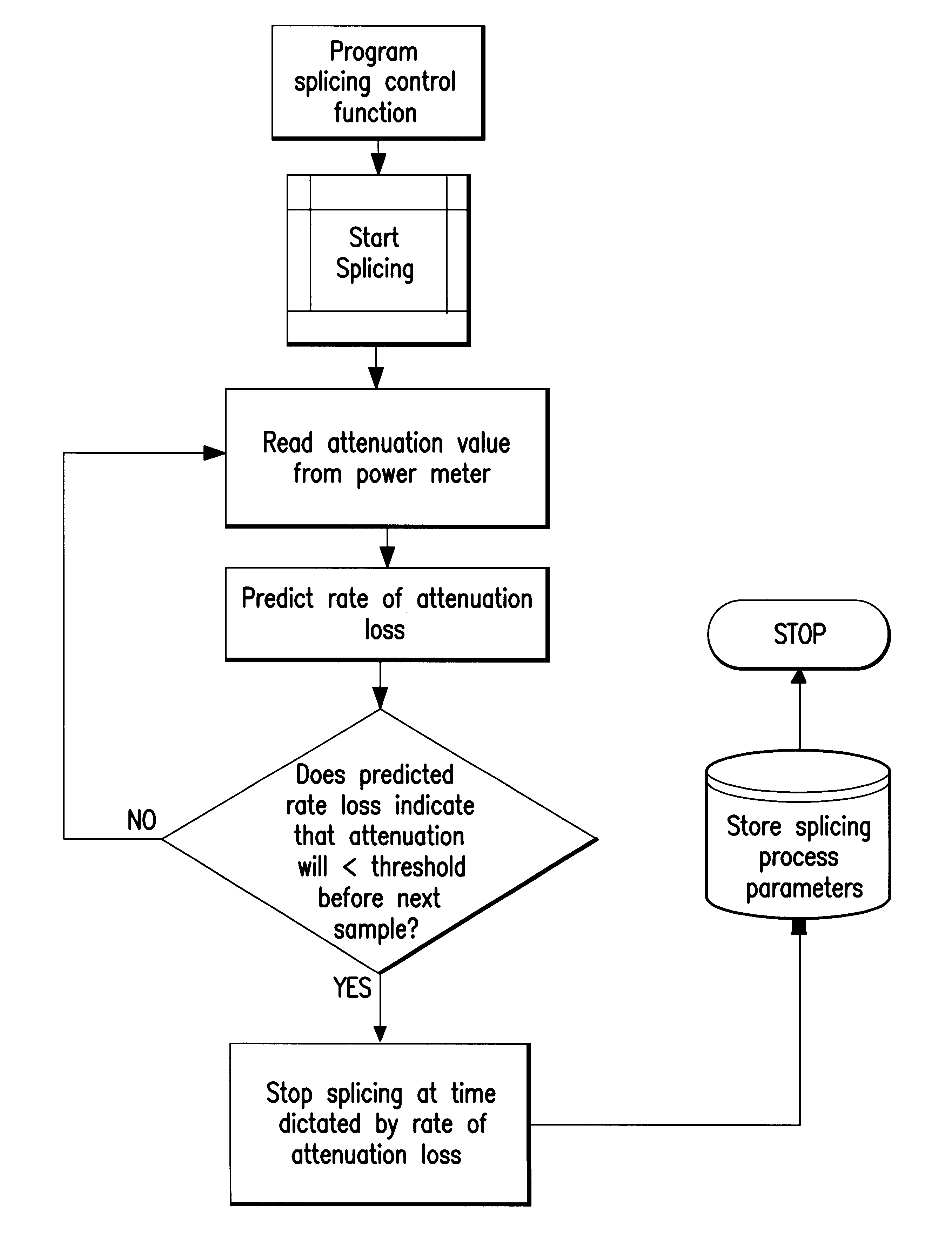
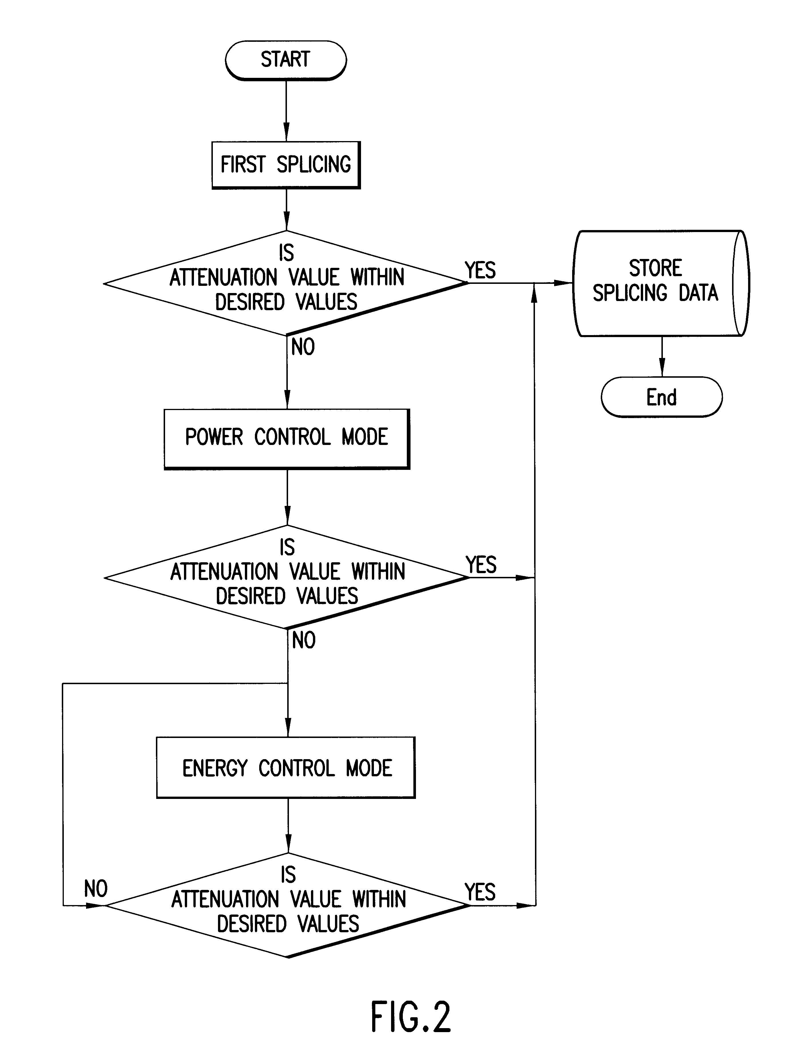
The high-level flowchart of FIG. 2 illustrates a combined methodology in which the inventive power control mode and energy control mode are utilized in conjunction and to advantage. This combined method may begin with a first splicing process which is a conventional splicing process that splices two fibers together. There is a chance, albeit quite small, that the conventional splicing operation will produce a splice with the desired insertion loss. This small probability is tested and, if the splice has an attenuation value within the desired values, splicing data is stored by the controller 10 in the memory device 50 and the process ends.

The splicing data stored in FIG. 2 includes a splicing recipe. Conventional splicing operations typically utilize a splicing recipe which may include a large number of parameters. These parameters inc...

second embodiment

The second embodiment includes algorithms that estimate the transient attenuation difference value which is also called the "final jump" value because the measured attenuation value takes a final jump after the splicer 30 is turned off.

FIG. 13 illustrates the final jump. The attenuation splicing graph of FIG. 13 also shows the attenuation value (negative values are graphed) as a function of time during the attenuation splicing process. The diamond shaped indicia indicate attenuation values read by power meter 40.

Preferably an initial reading is taken before splicing starts. The attenuation value typically drops off sharply once splicing starts as shown in FIG. 13. This drop-off or initial jump may be measured by taking the difference between the initial reading and a reading just after the splicer 30 is turned on. The attenuation value then begins to fall (the graph plots negative attenuation values). From these values, the rate of change or slope can also be determined. As further ...


PUM

PropertyMeasurementUnit
insertion lossaaaaaaaaaa
poweraaaaaaaaaa
energyaaaaaaaaaa

Abstract

A method of controlling an optical fiber splicing machine utilizes a power control mode to control the amount of power delivered to fuse the fibers. In the power control mode, the attenuation is measured while the fusing process is occurring. A rate of attenuation loss is predicted from the measured attenuation values by using an estimator. If the rate of attenuation loss indicates that a threshold insertion loss will be crossed before the next attenuation measurement, the splicing machine is stopped prior to the next attenuation measurement. If the desired attenuation is not achieved, an energy control mode is utilized which controls the amount of energy delivered to fuse the fibers. After delivering this energy, the method measures the attenuation. If not within desired values, the energy mode is repeated. At each iteration the splicing control function utilized by the energy control mode may be reprogrammed. A PID control formula may be used to determine the arc current for each iteration. A system for performing the attenuating splice uses, in addition to an optical fiber splicing machine, a laser and power meter to measure insertion loss as well as a controller to implement the splicing methods.

Description

1. Field of InventionThis invention generally relates to fiber optics and, more particularly, to fiber splices, fiber splicing machines and methods therefore.2. Description of Related ArtConventional splicing operations and equipment are designed to minimize or eliminate optical signal attenuation. To that end, conventional splicing machines are designed to bring the two fibers into as perfect an alignment as possible. This goal of achieving optimum alignment between the fibers is met by utilizing various detectors and fine alignment control functions so that the fibers are aligned. Typically, the respective optical axes are aligned first and then the fibers are brought together so that their ends are in direct contact.Conventional splicing machines utilize an electric arc to fuse the fibers. Such machines permit an operator to set fusing current, fusing time and fine tune fiber alignment to achieve the best alignment possible between the fibers. Such conventional splicing machines ...

Claims


Application Information

Patent Timeline
Patent Type & Authority Patents(United States)
IPC IPC(8): G02B6/255G02B6/26
CPCG02B6/2551G02B6/266
Inventor YANG, YAGUANGMAHMOOD, WAQARSAHINCI, ERIN
Owner CIENA
Why Eureka
Try Eureka