Ink jet head

a jet head and jet head technology, applied in the field of jet head, can solve the problems of large amount of ink consumed, poor recording quality, and large volume of ink consumption, and achieve the effect of improving the recording quality, reducing the volume of ink consumption, and improving the quality of ink consumption

Inactive Publication Date: 2004-02-03
BROTHER KOGYO KK
View PDF5 Cites 41 Cited by
  • Summary
  • Abstract
  • Description
  • Claims
  • Application Information

AI Technical Summary

Benefits of technology

It is another objective of the present invention to provide a compact and simple configuration that enables stably maintaining and recovering good ejection characteristics of an ink jet head without unnecessarily wasting a great amount of ink.
It is still another objective of the present invention to overcome the above-described problems and to provide an ink jet head with a simple structure that reduces the amount of clogging in pressure chambers and nozzle orifices caused by dust and other debris that entered the ink jet head during production of the ink jet head.
With this configuration, pressure fluctuations are absorbed by the region with weak mechanical stiffness. Also, all the pressure chamber have uniform mechanical stiffness so that pressure generated in the pressure chambers is uniform and good-quality recording can be realized.
Pressure waves are generated when the pressure chambers operate to eject ink. The pressure waves can propagate into the common ink chamber in association with ink flow. With the configuration of the second aspect of the present invention, pressure waves that propagate into common ink chamber are dampened by the broad-width region. Therefore, pressure fluctuations in the common ink chamber can be reduced and ink ejection characteristics can be stabilized.
With this configuration, ink can be supplied into the ink-supply-connection opening of one of the circulation channel and the common ink chamber and discharged through the ink-supply-connection opening of the other one of the circulation channel and the common ink chamber. As a result, air bubbles in the ink can be returned to the ink supply source along with the ink, so that ink supplied from the common ink chamber to the pressure chambers has less air bubbles. Accordingly, a compact and simple configuration that enables stably maintaining and recovering good ejection characteristics of an ink jet head without unnecessarily wasting a great amount of ink can be made.
With this configuration, because the filter holes are interposed between the pressure chambers and the common ink chamber, dust and other debris that entered the ink jet head during manufacture of the ink jet head is less likely to flow from the common ink chamber into the pressure chambers and accumulate in the channel between the common ink chamber and the pressure chamber. Accordingly, clogs in the pressure chambers and the nozzle orifices can also be prevented. Also, the filters can be easily provided to all of the pressure chambers by sandwiching the third substrate, which is formed with the filter holes, between the first substrate, which is formed with the pressure chambers, and the second substrate, which is formed with the common ink chamber.

Problems solved by technology

The resultant pressure fluctuations in the common ink chamber can adversely influence subsequent ink ejections, resulting in poor recording quality.
However, this configuration has a disadvantage in that all of the ink in the common ink chamber and a portion of the ink in the ink tank are sucked into the cap, so that a relatively large amount of ink is consumed.
However, because the two tubes must be connected to either end of the common ink chamber, the structure of the ink jet head is complicated and also bulky.
Such debris cannot be removed by the filter and so can clog up the pressure chambers and the nozzle orifices.
However, it would be difficult to manufacture an ink jet head with a soft film mounted on a portion of the ink jet head.
When the mechanical stiffness of the pressure chambers lacks uniformity, pressure generated in the pressure chambers can also vary so that ink ejection also lacks uniformity

Method used


Image

  • Ink jet head
  • Ink jet head
  • Ink jet head

Examples


Embodiment Construction

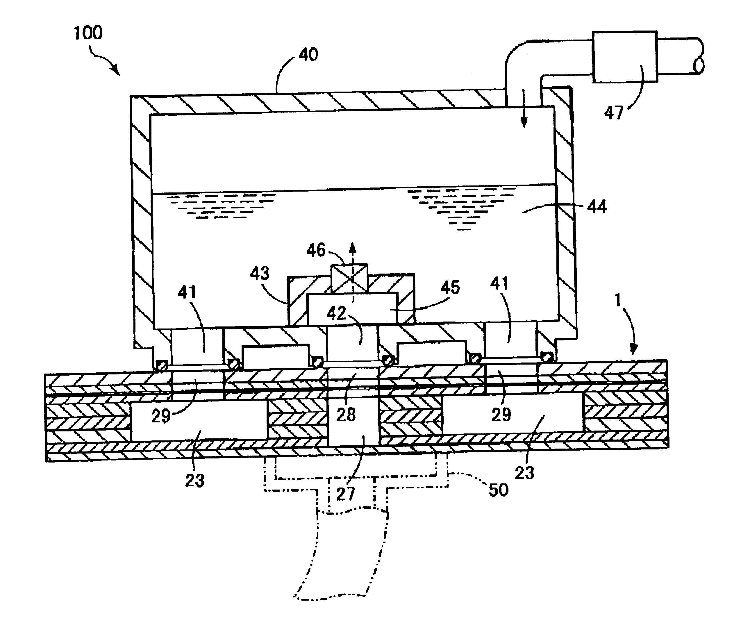
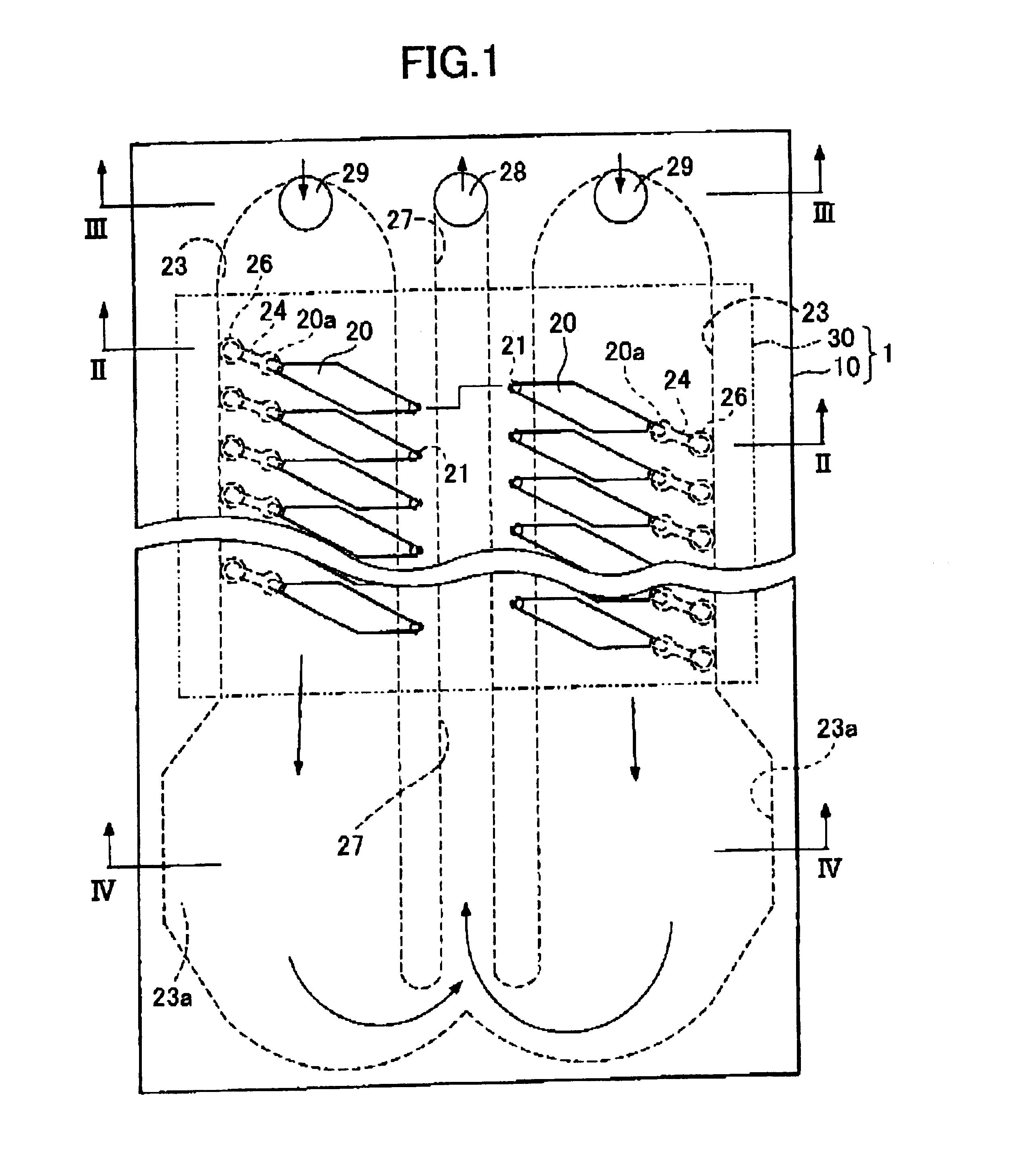
Next, an ink jet head 1 according to an embodiment of the present invention will be described with reference to the attached drawings. As shown in FIG. 1, the ink jet head 1 includes a cavity plate set 10 and an actuator unit actuator 30 stacked on top of each other.

The cavity plate set 10 is Formed with a plurality of pressure chambers 20, two common ink chambers 23, 23, nozzle orifices 21, a circulation channel 27, and various other ink channels for bringing these into fluid communication with each other. As shown in FIG. 2, the cavity plate set 10 is configured from first through ninth substrates 11 to 19 adhered to each other in a laminated stack, with the first substrate 11 at the top of the stack and the ninth substrate 19 at the bottom of the stack. Each of the substrates 11 to 19 is formed with openings using etching. When the substrates 11 to 19 are stacked together to form the cavity plate set 10, the openings in the substrates configure the pressure chambers 20, the nozzl...


PUM


Abstract

An ink jet head includes rows of pressure chambers, a common ink chamber, and a circulation channel. Filter holes are provided along a fluid channel connecting the common ink chamber with the pressure chambers. The common ink chamber is formed broader at a region separated from, and with a weaker mechanical stiffness than, the portion that is connected to the pressure chambers. The common ink chamber and the circulation channel are elongated in the direction that the pressure chamber rows extend. The circulation channel and the common ink chamber are in fluid communication with each other at one lengthwise end and both have an opening at the opposite lengthwise end to enable connection to the external ink supply.

Description

1. Field of the InventionThe present invention relates to an ink jet head.2. Description of the Related ArtA typical ink jet head is formed with a plurality of pressure chambers in fluid communication with a common ink chamber. The common ink charter is supplied with ink from an ink tank and distributes the ink to the pressure chambers. Pressure is applied to ink in selected ones of the pressure chambers to eject ink droplets from nozzles orifices that are in fluid communication with the pressure chambers.A pressure wave is generated when pressure is applied to ink in one of the pressure chamber. The pressure wave can propagate into the common ink chamber. The resultant pressure fluctuations in the common ink chamber can adversely influence subsequent ink ejections, resulting in poor recording quality.Ink jet printers are typically provided with a recovery unit. The recovery unit is used to remove dust or other material that might or does clog up channels or nozzle orifices. By prov...

Claims


Application Information

Patent Timeline
Patent Type & Authority Patents(United States)
IPC IPC(8): B41J2/14B41J2/175
CPCB41J2/14209B41J2/1753B41J2/17553B41J2002/14306B41J2002/14403B41J2002/14419B41J2202/12
Inventor HIROTA, ATSUSHI
Owner BROTHER KOGYO KK
Why Eureka
Try Eureka