Printed circuit board and connector assembly

a technology of printed circuit board and connector, which is applied in the direction of printed circuit, electrical equipment, coupling device connection, etc., can solve the problems of requiring a relatively large amount of space, unable to achieve proper connection, and damaged zero-force connector on printed circuit board

Inactive Publication Date: 2004-02-24
TYCO ELECTRONICS BELGIUM EC
View PDF7 Cites 12 Cited by
  • Summary
  • Abstract
  • Description
  • Claims
  • Application Information

AI Technical Summary

Benefits of technology

Printed circuit board zero force connectors have the particular feature that their contact elements are arranged on one or more movable parts and can be moved together with them. By moving the parts carrying the contact element, the printed circuit board zero force connector can be brought from an assembly position allowing an printed circuit board to be plugged into, or removed from a connecting position without the contacts touching the printed circuit board (zero insertion force). The parts carrying the contact elements may then be moved by the actuation of an actuating mechanism, for example a rod, which is mounted externally on the printed circuit board zero force connector and / or on the printed circuit board, so the connection is made. An actuating mechanism of this type requires a relatively large amount of space and also has to be operated following quite specific sequencing; otherwise, the printed circuit board and / or the printed circuit board zero force connector can be damaged and / or a proper connection is not achieved. This is a considerable drawback of printed circuit board zero force connectors. It is therefore an object of the present invention to find an option by which printed circuit board zero force connectors can be produced more compactly and easily and can be operated more reliably.
As a result of the proposed innovations, printed circuit board zero force connectors can be produced compactly, easily, with less complenty, and can be operated more reliably. Advantageous developments of the invention can be inferred from the sub-claims, the following description and the figures.

Problems solved by technology

An actuating mechanism of this type requires a relatively large amount of space and also has to be operated following quite specific sequencing; otherwise, the printed circuit board and / or the printed circuit board zero force connector can be damaged and / or a proper connection is not achieved.
This is a considerable drawback of printed circuit board zero force connectors.
This possibility can never be completely ruled out in conventional printed circuit board connectors and when it occurs will sooner or later damage and / or reduce the functioning of the printed circuit board and / or of the printed circuit board connector.

Method used


Image

  • Printed circuit board and connector assembly
  • Printed circuit board and connector assembly
  • Printed circuit board and connector assembly

Examples


Embodiment Construction

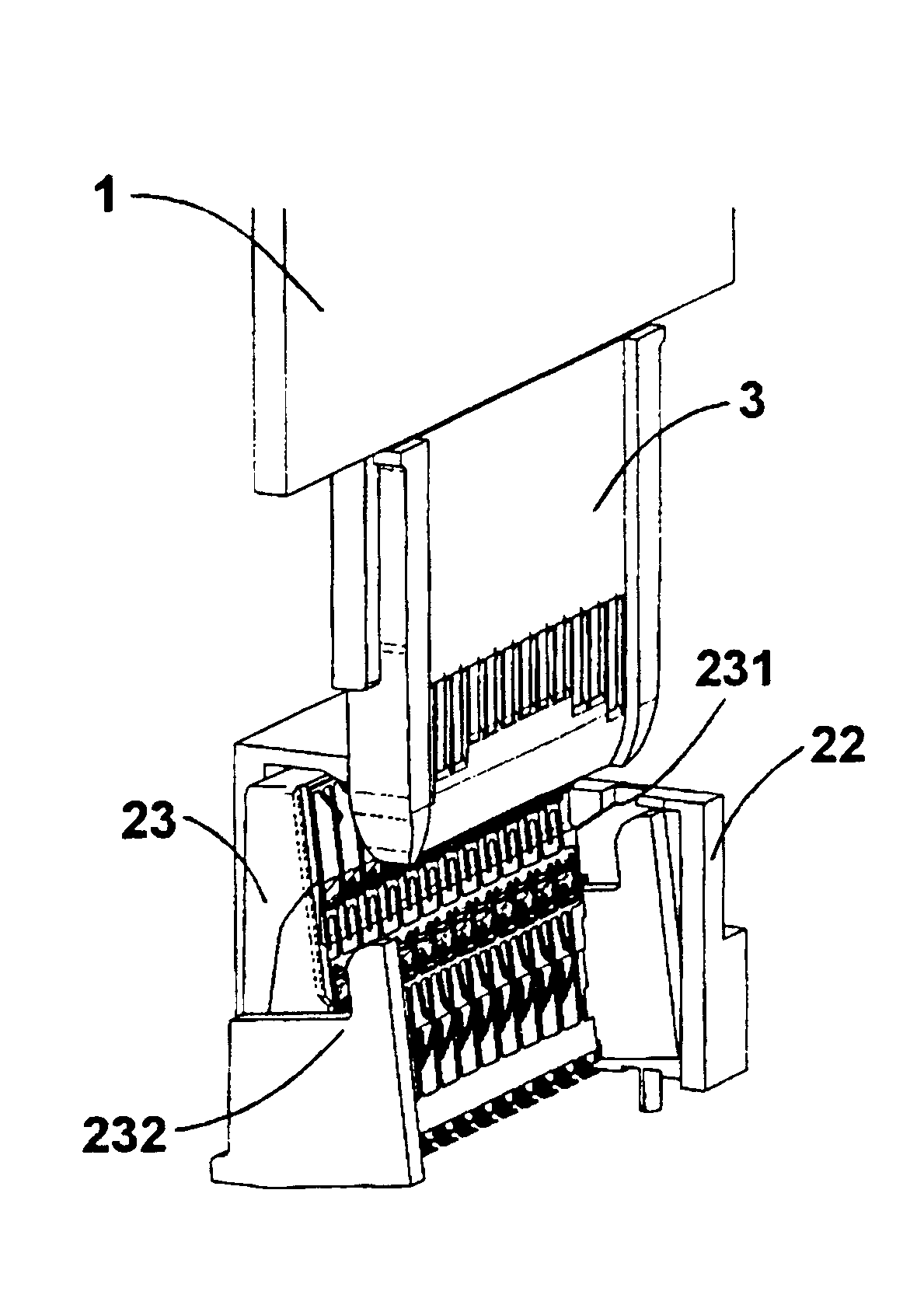
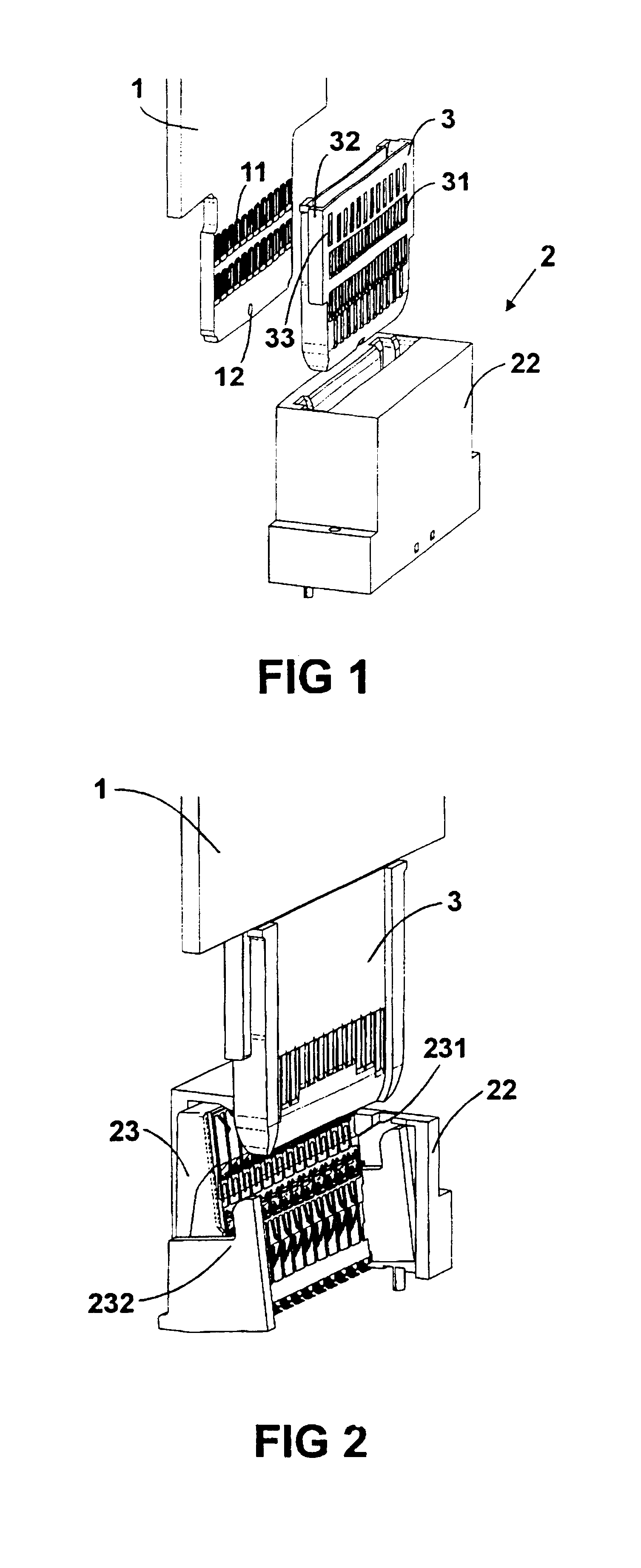
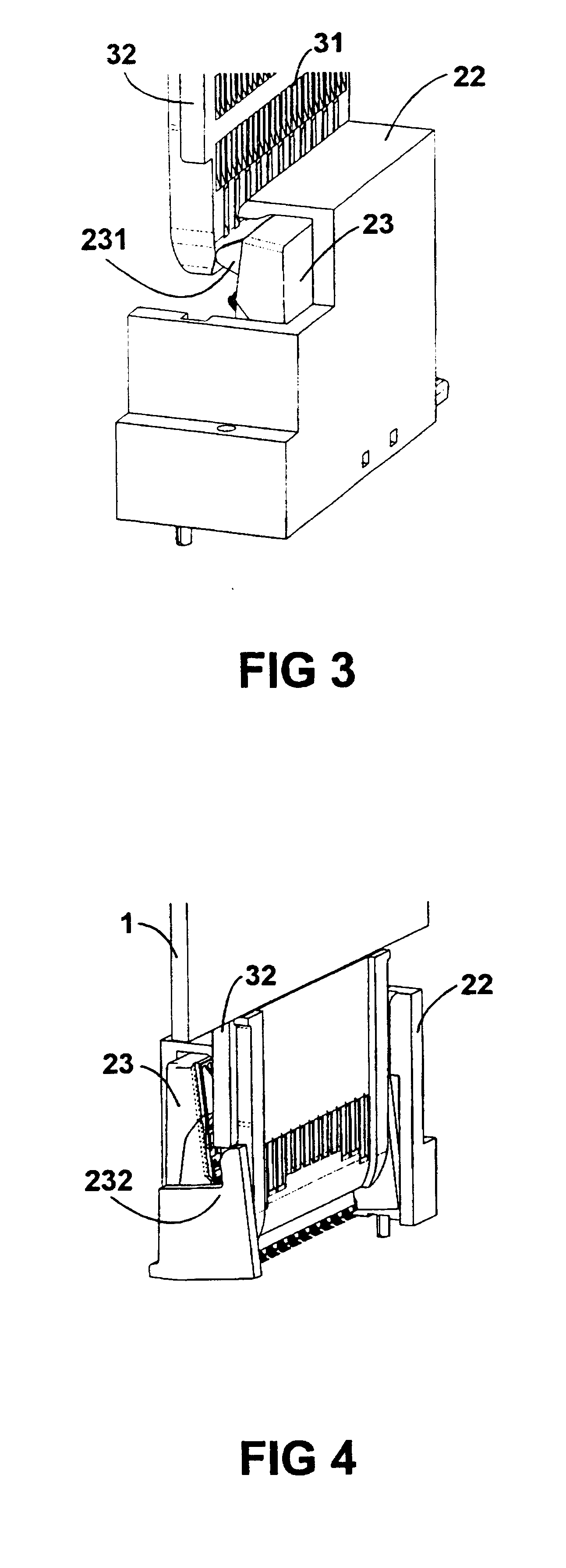
The printed circuit board described hereinafter is a printed circuit board which is designed to be connected via a printed circuit board zero force connector to another printed circuit board or a different component of the system containing the printed circuit board. The printed circuit board is connected to the printed circuit board zero force connector via surface contacts provided on the printed circuit board. The surface contacts are arranged in such a way that they can be contacted by contact elements of a printed circuit board zero force connector. The printed circuit board zero force connector is normally mounted on another printed circuit board (not shown in the figures) to which it is desired that the currently considered printed circuit board is to be connected.

For the sake of completeness, it is mentioned at this point that only the components of the considered printed circuit board and of the considered printed circuit board zero force connector, which are of particular ...


PUM


Abstract

A printed circuit board and a printed circuit board zero force connector are configured such that the printed circuit board zero force connector is properly actuated automatically by an attachment provided on the printed circuit board when the printed circuit board is plugged into and removed from the printed circuit board zero force connector.

Description

1. Filed of the InventionThe invention relates to a printed circuit board and a printed circuit board zero force connector.2. Description of Related ArtCountless embodiments of printed circuit board assemblies of the aforementioned type have been known for many years. Printed circuit board connectors are used for connecting to printed circuit boards. In particular, if a very large number of surface contacts on the printed circuit board are to be contacted by associated contact elements of the printed circuit board connector, it is known to use so-called printed circuit board zero force connectors. Printed circuit board zero force connectors have likewise been known for many years in countless embodiments and are described, for example, in DE 195 11 509 A1, DE 197 25 123 A1, DE 197 25 132 A1 and DE 197 25 138 A1.U.S. Pat. No. 5,160,275 describes a printed circuit board and connector assembly, comprising a printed circuit board with surface contacts arranged thereupon and a printed ci...

Claims


Application Information

Patent Timeline
Patent Type & Authority Patents(United States)
IPC IPC(8): H01R12/16H01R12/00H05K1/11H01R12/87H01R13/629H01R24/00
CPCH05K1/117H01R12/87H05K2201/2027
Inventor LONGUEVILLE, JACQUESOCKET, TOMHOOLHORST, ALBERT
Owner TYCO ELECTRONICS BELGIUM EC
Why Eureka
Try Eureka