Electric ARC welder and controller to design the waveform therefor

a controller and waveform technology, applied in the field of electric arc welders, can solve the problems of limited on-site adjustments, and achieve the effect of simplifying operator manipulation of display parameters and waveforms

Inactive Publication Date: 2004-03-02
LINCOLN GLOBAL INC
View PDF6 Cites 79 Cited by
  • Summary
  • Abstract
  • Description
  • Claims
  • Application Information

AI Technical Summary

Benefits of technology

Another object of the present invention is the provision of a controller, as defined above, which controller can read the operating parameters of the welder to display the waveform and various operating parameters and allowing simplified operator manipulation of the display parameters and the waveform.

Problems solved by technology

This successful controller had a certain amount of adjustability in the field; however, such on-site adjustments were limited.

Method used


Image

  • Electric ARC welder and controller to design the waveform therefor
  • Electric ARC welder and controller to design the waveform therefor
  • Electric ARC welder and controller to design the waveform therefor

Examples


Embodiment Construction

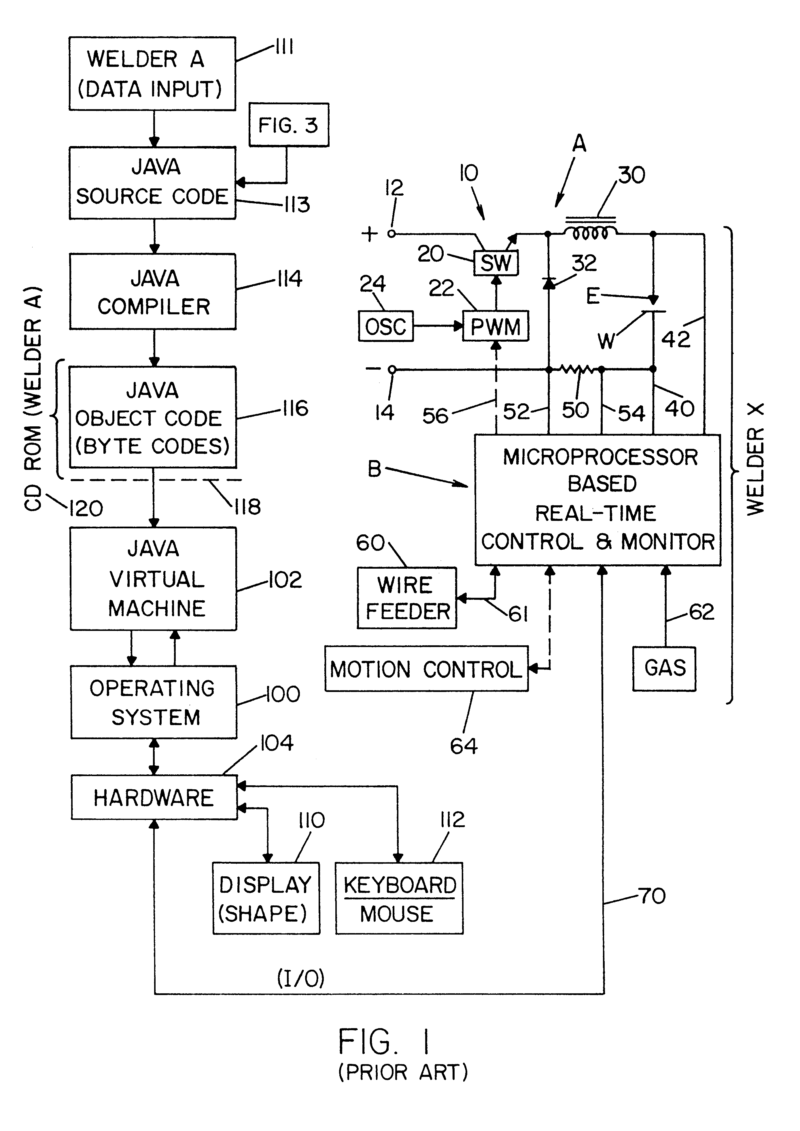
Referring now to the drawings, wherein the showings are for the purpose of illustrating the preferred embodiment of the present invention and not for the purpose of limiting same, FIG. 1 shows the prior art of Hsu U.S. Pat. No. 6,002,104. An electric arc welder A controlled by a somewhat standard microprocessor based controller B which is a real time control and monitor for welder A. Controller B is combined with welder A as a commercial product purchased for use in various welding processes, especially for mass production welding of consumer products, which welding is often done by a robot. The stand alone unit incorporating welder A and controller B uses any of a number of switching type power supplies, such as an inverter generally illustrated in Blankenship U.S. Pat. No. 5,349,157 or a buck converter or down chopper as generally shown in Stava U.S. Pat. No. 4,952,064. For the purposes of simplicity, welder A is shown as including a down chopper as part of power supply 10 which i...


PUM

PropertyMeasurementUnit
switching frequencyaaaaaaaaaa
currentaaaaaaaaaa
graphic interface computeraaaaaaaaaa

Abstract

An electric arc welder for creating a welding cycle with a real time current waveform constituting several control parameters by a microprocessor that controls a power supply by a signal so the output of the power supply traces a desired waveform and dynamic reaction behavior to arc conditions defined by the control parameters. The welder has a controller for creating the signal and reading the parameters, a graphic user interface program controlled by input from a graphic user interface computer, a system with a first interface for an interactive display for displaying the desired waveform and dynamic behavior and at least one manipulative control parameter, a second interface for a manual data entry device to change the waveform and/or the parameters and a digital communication link from the graphic user interface to the welder microprocessor controller for causing the welder to perform the desired waveform by controlling the signal. A number of script language files each defining a given type of waveform logic and containing a user manipulative variable table of control parameters and graphical descriptive language to display a waveform to be implemented by the welder is used with an input stage for processing a selected one of the script files into graphic user interface components (readouts, charts, and/or panels) for operating the welder.

Description

The present invention relates to the art of electric arc welding with a welder having a power supply of the switching type and more particularly to an electric arc welder of this type combined with a novel and unique controller to design the waveform.BACKGROUND OF INVENTION AND INCORPORATION BY REFERENCEElectric arc welding involves the movement of an electrode toward a workpiece while current is passed through the electrode and across an arc between the electrode and workpiece. Although some electric arc welders utilize a non-consumable electrode, most of the mass production arc welding involves an electrode which is consumed during the welding process whereby the electrode is melted by the arc and deposited on the workpiece. Thus, an arc welding process includes variable process characteristics, such as wire speed or electrode speed, gas composition, electrode diameter and workpiece metal. The actual electrical arc welding process at the production site takes into consideration th...

Claims


Application Information

Patent Timeline
Patent Type & Authority Patents(United States)
IPC IPC(8): B23K9/10B23K9/09
CPCB23K9/09B23K9/092B23K9/1006B23K9/1062
Inventor HSU, CHRISTOPHERPETERS, STEVEN R.
Owner LINCOLN GLOBAL INC
Why Eureka
Try Eureka