Radio communication system for push information delivery

a radio communication system and information delivery technology, applied in the field of network-based radio communication systems, can solve the problems of increasing network traffic, not being able to deliver the necessary information to people in need of that information, and not being able to provide the push-type service to those clients operating with a lan using conventional technology

Inactive Publication Date: 2004-03-09
MITSUBISHI MATERIALS CORP
View PDF5 Cites 87 Cited by
  • Summary
  • Abstract
  • Description
  • Claims
  • Application Information

AI Technical Summary

Problems solved by technology

When such information delivery requests are output to the host at short intervals, it leads to increase in the network traffic volume.
However, because the conventional broadcasting technology can only distribute identical information simultaneously, there is a problem that it can not deliver the necessary information to people in need of that information.
Also, there is a problem that, to deliver information needed only by the receiver, the conventional technology must individually deliver pieces of information.
But, it has not been possible to provide the push-type service to those clients operating with a LAN using the conventional technology.
This is because, in the case of a router with the NAT function, for example, because IP addresses are allocated in response to client access requests, it has not been possible to

Method used


Image

  • Radio communication system for push information delivery
  • Radio communication system for push information delivery
  • Radio communication system for push information delivery

Examples


embodiment 1

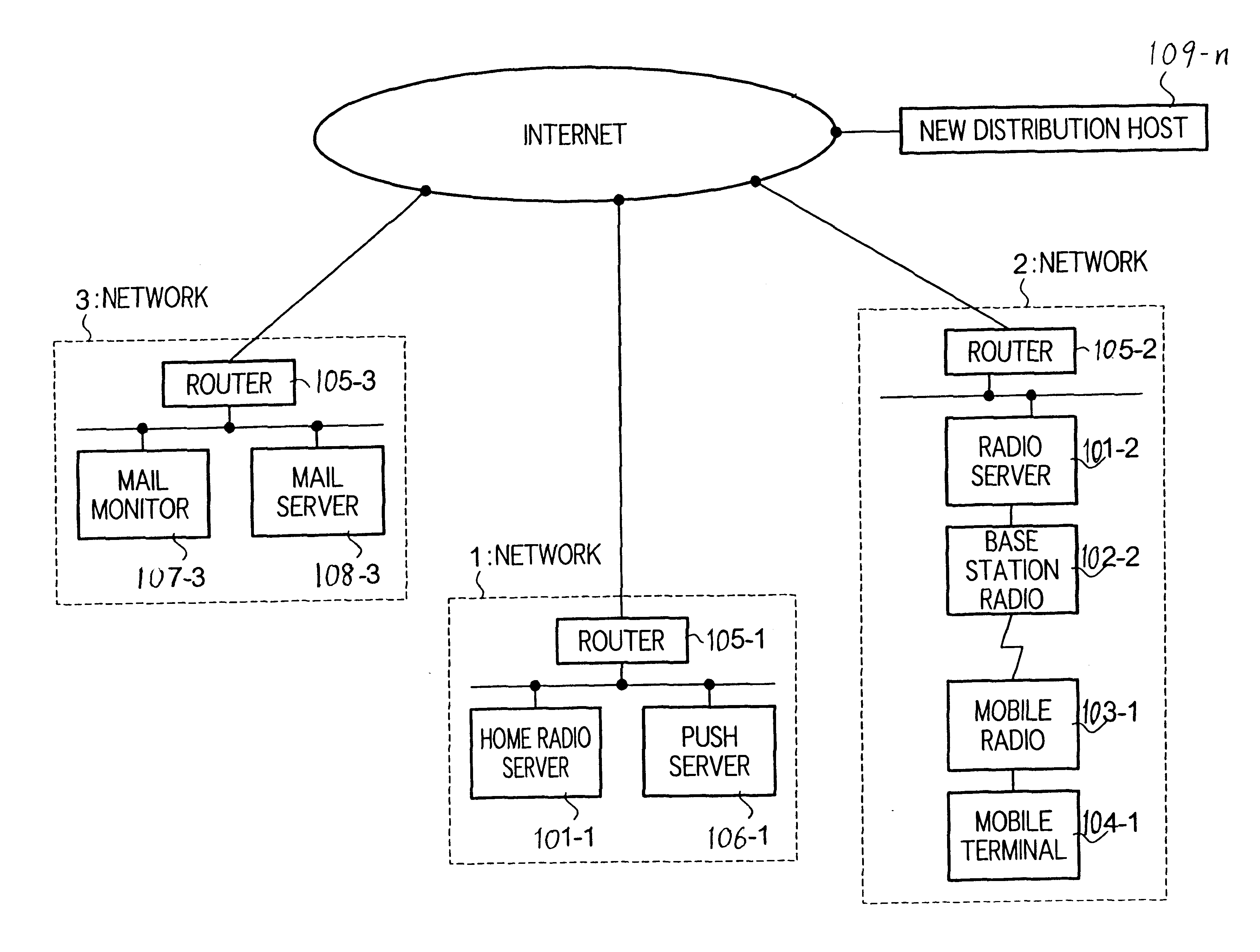
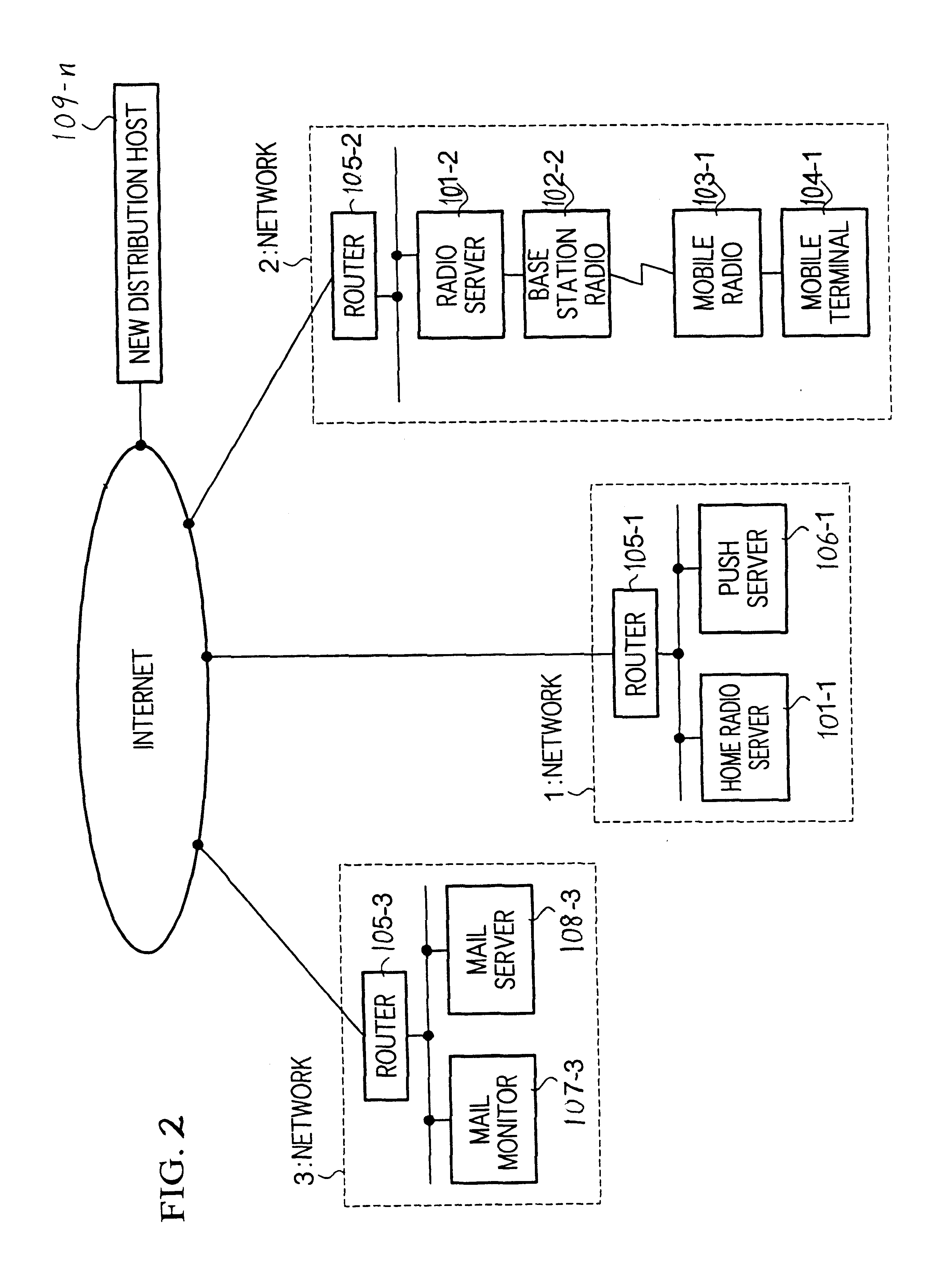
FIG. 1 is a block diagram of a structure of the push function server 106-n in In this embodiment, explanations relate to the case in which a plurality of networks n (n=1, 2, . . . ) are connected to the Internet for its use. It should also be noted that the communication protocol is not necessary to be limited to TCP / IP.

The push function server 106-n in this embodiment is comprised by: a processing section 111-n having a mobile radio address acquiring section 114-n and an information distribution section 115-n; an information accumulation section 112-n for storing identifier information for the mobile terminal 104-n to which data should be directed and information to be distributed; and an input / output (I / O) section 113-n (n=1, 2, . . . ) connected to the network for exchanging data. The identifier information may include: (1) a combination of the subscriber group number, mobile radio number, terminal IP address, or (2) a combination of the subscriber group number and mobile radio ...

embodiment 2

Next, the mail monitor (information monitoring device) which represents Embodiment 2 of this invention will be explained with reference to the drawing.

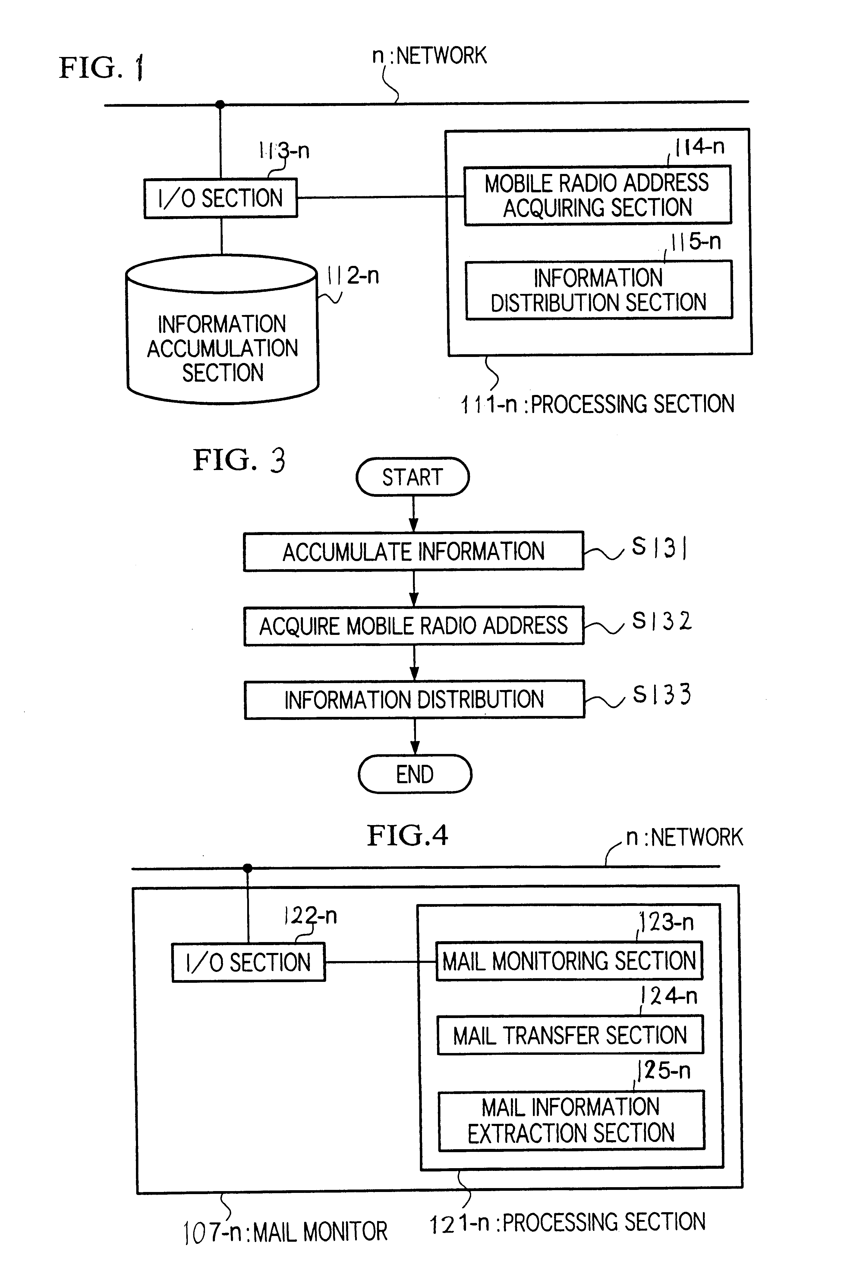
FIG. 4 shows a block diagram of the mail monitor 107-n in this embodiment. In this embodiment, it is assumed that a plurality of networks (n=1, 2, . . . ) are connected to the Internet. Also, it is assumed that TCP / IC is used as the communication protocol, but it is not necessary to limit to this protocol only. Also, information to be monitored is e-mails in this embodiment, but it is acceptable to monitor servers other than the mail server 108. Here, the mail monitor 107-n in this embodiment is used in conjunction with the push server 106-n in the previous embodiment.

The mail monitor 107-n in this embodiment is comprised by: a processing section 121-n having a mail monitoring section 123-n, a mail transfer section 124-n, a mail information extraction section 125-n; and an I / O section 122-n connected to the networks n for exchanging d...

embodiment 3

In the following, a terminal device and a computer server in Embodiment 3 will be explained with reference to the drawings.

FIG. 6 shows a block diagram of the overall radio communication network system in Embodiment 3. In this diagram, the reference numeral 201 relates to a broadcast terminal to build and dispatch information to be broadcast; 202 refers to a computer server (server hereinbelow) connected by a network 205; 203-1.about.4 are base station radios (base stations hereinbelow) connected to the server 202; 204-1.about.4 are mobile terminals for establishing radio communications with respective base stations 203-1.about.4.

Here, four base stations 203-1.about.4 are shown for one server 202 but more than five base stations may be connected.

Also, one base station 203-1 corresponds to on mobile terminal 204-1, but it is permissible to establish communication to one base station 203 using more than two mobile terminals 204.

Next, the operation to broadcast information from a broad...


PUM


Abstract

To realize real-time information distribution and a server that reliably delivers information to a mobile terminal and a push-type control method for an information monitoring device.The push-type function server of this invention accumulates information to be distributed and identifier information of destination terminal devices; obtains address information of a terminal device from a home radio server that manages the terminal device according to the identifier information, and transfers distributed information to a radio server connected to a destination terminal device based on the address information, and the information monitoring device monitors whether or not data to be distributed to a specified terminal device have been delivered to other information-storing severs.

Description

TECHNOLOGICAL FIELDThis invention relates to a network-based radio communication system such as the Internet, and provides an apparatus that can be connected to the Internet by radio signals and having a processing sequence for distributing push-type information to mobile terminals and a method for control of such a system.TECHNOLOGICAL BACKGROUNDIn recent years, Internet-based push-type information distribution services are being provided. Such a push-type information distribution is meant to automatically deliver information at certain times from the host side to terminal devices as clients, but, in reality, the terminal device collects information from the host by requesting delivery of information at specific times. That is, in practice, the delivery method is operated not as a push-type control but as a pull-type control.In the meantime, needs for mobile computing are increasing and contact to the Internet is currently carried out from the mobile terminal device. In mobile comp...

Claims


Application Information

Patent Timeline
IPC IPC(8): H04L29/06H04L29/12H04L12/18H04L12/58H04L12/28H04L29/08
CPCH04L12/1859H04L29/06H04L29/12009H04L29/1233H04L61/25H04W4/00H04L67/26H04L67/18H04L12/189H04W8/26H04W24/00H04W88/02H04W88/08H04W88/14H04L67/42H04L61/00H04L67/55H04L67/52H04L9/40H04L67/01
Inventor TARI, KAZUYOSHIUNOKI, HIROKAZUNAGIRA, TUMORU
Owner MITSUBISHI MATERIALS CORP
Why Eureka
Try Eureka