Control of series-resonant inductive pickups

a series-resonant inductive pickup and pickup technology, applied in the direction of ac-dc conversion, efficient power electronics conversion, electric vehicles, etc., can solve the problem that the induced resonant current may substantially die away

Inactive Publication Date: 2004-03-16
AUCKLAND UNISERVICES LTD
View PDF5 Cites 55 Cited by
  • Summary
  • Abstract
  • Description
  • Claims
  • Application Information

AI Technical Summary

Benefits of technology

Preferably the switch controlling means is also capable of responding to the instantaneous voltage levels present at each side of the switching means and h

Problems solved by technology

Preferably a repetitive cyclic operation of the switching means is relatively slow, so th

Method used


Image

  • Control of series-resonant inductive pickups
  • Control of series-resonant inductive pickups
  • Control of series-resonant inductive pickups

Examples


example 1

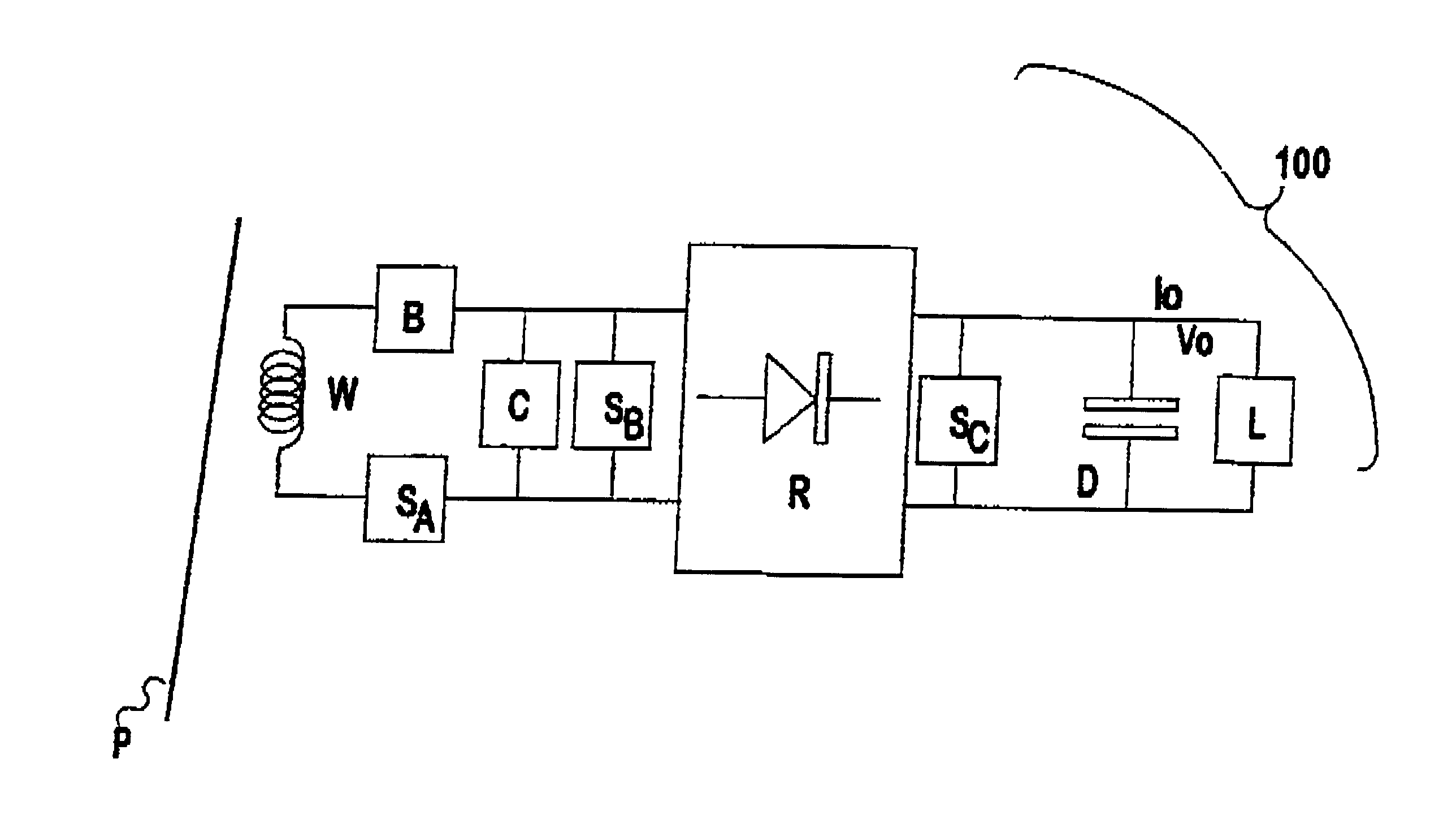
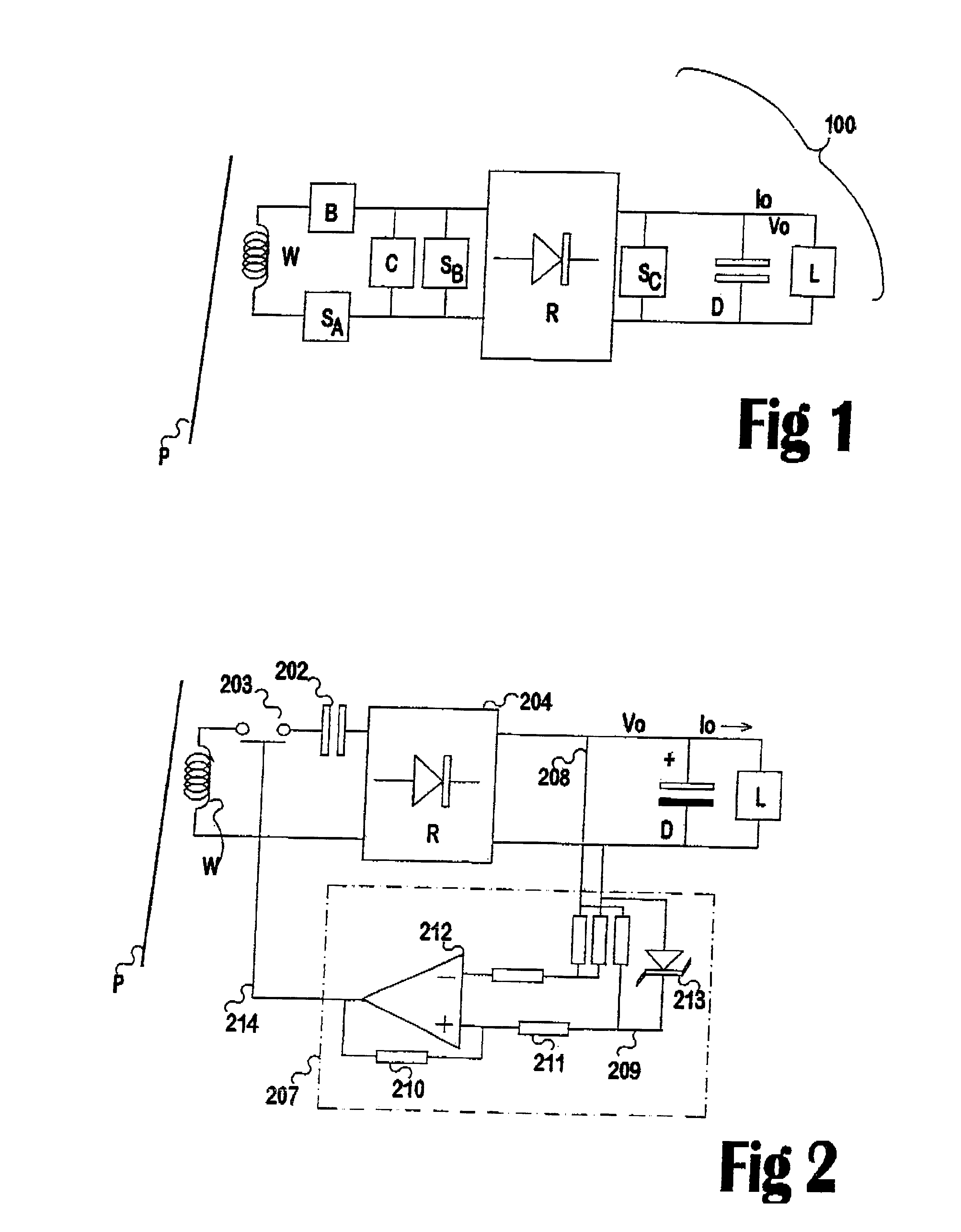
This invention relates to a secondary pickup having for control purposes a combination of major circuit components. See FIG. 1, in which the circuit elements to the left of the rectifier R are: a pickup winding W capable of intercepting a magnetic field surrounding a primary inductive conductor P a resonant circuit (of inductor W and series resonating capacitor B) are present at an input of the rectifier R. Note that C and S.sub.B comprise elements of the prior art shortable parallel-tuned pickup (which lacks items B and S.sub.A). They do not exist within the prototype series-tuned, controllable pickup.

A second circuit is located at an output of the rectifier R, generally including a load L (which may be variable) and a smoothing capacitor D. S.sub.C is an alternative position for a shorting switch for a parallel-tuned circuit. Most loads require a supply of DC, or sometimes of AC of a frequency other than that of the primary trackway (such as for use by induction motors).

The genera...

example 2

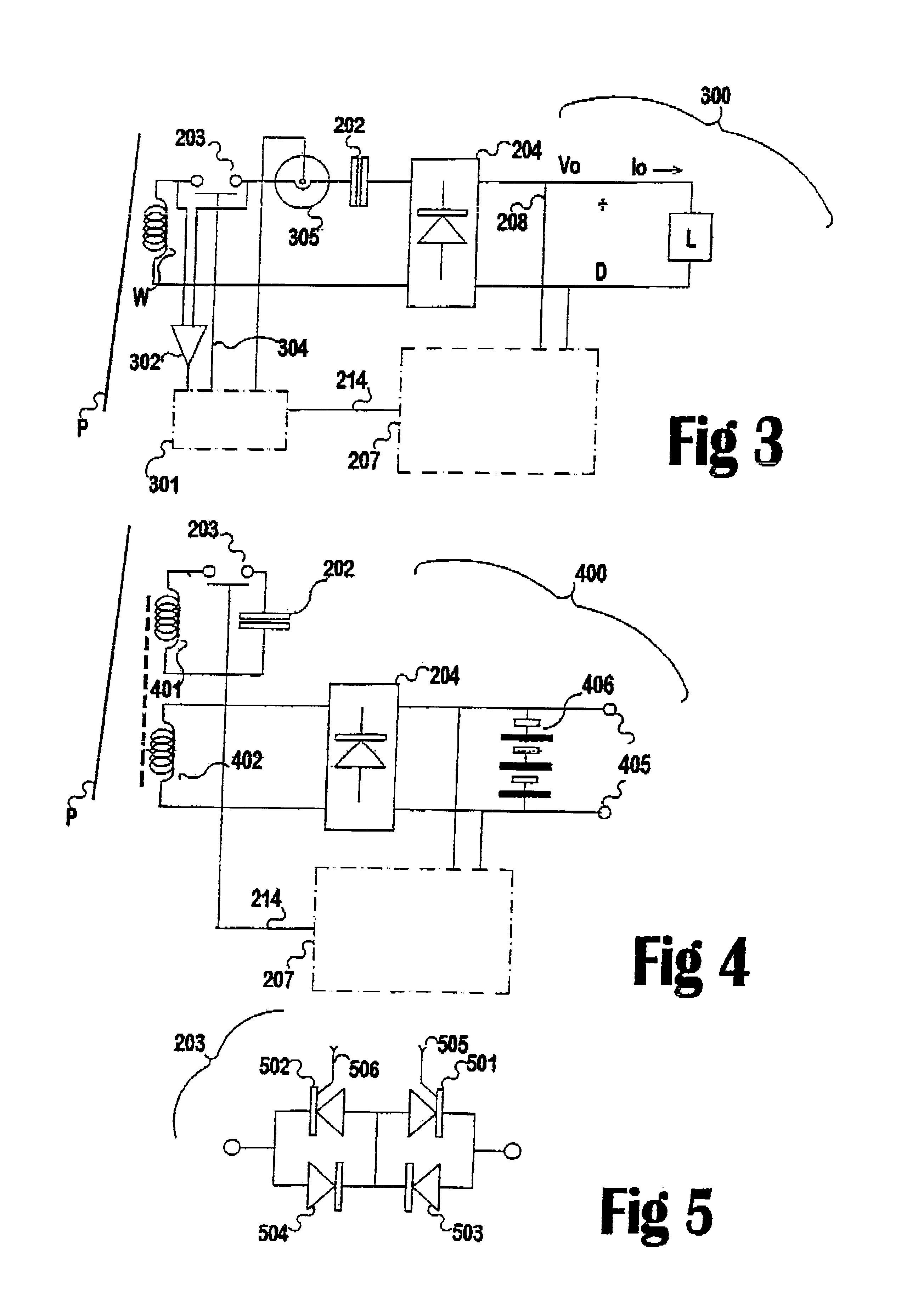
FIG. 4 illustrates an optimised pickup arrangement suitable for example in the charging of batteries in which a first, high-voltage winding 401 is provided with a series tuned resonating capacitor 202 and a switch 203 capable of opening or closing fee circuit as described previously in this section. A second, low-voltage circuit comprises a simple coil 402 (the windings of which may in practice comprise a single turn) directly wired to a rectifier 204 which in turn feeds a battery module or monobloc 406. Control of the circuit (through block 207 and optionally also a block like 301 (details not shown)) may be either by supplied or drawn current or by voltage measurements of the across-battery voltage (or both). Coils 401 and 402 share a common core and when 401 is unable to resonate, the output of 402 is substantially reduced. This configuration has the advantage that the series switch is not required to interrupt a high current. Heavy current devices are more expensive than high vo...


PUM


Abstract

A series resonant inductive pickup has a bi-directional solid state switch in series with an inductor and a capacitor is controlled by switch control elements capable of causing the switching elements to repetitively be in either an open or a closed state, so that by varying the closed: open ratio of the switch the time-averaged amount of power picked up by the power pickup can be controlled. Switch is controlled by output of a voltage comparing circuit. A reference voltage source provides a basis for comparison of some fraction of a supply voltage in order to cause the switch to operate. The magnitude of capacitance in relation to the current drawn by the load determines the repetition rate of ON or OFF commands to the switch. If the current drawn by the load tends to zero, the proportion of time during which the switch is open will tend to 100%.

Description

This invention relates to apparatus and methods for controlling the current in a resonant secondary or pickup circuit for an inductive power transfer circuit, capable of collecting electricity from a primary distribution pathway having one or more conductors carrying alternating current.In present day inductive power transfer (IPT) systems there is an energisable trackway having at least one conductor (the primary), each of which is surrounded by an alternating magnetic field during use One or more pickup devices, each of which includes at least one pickup winding, form part of the system. Each is placed so as to intercept a part of the alternating magnetic field of the primary and thereby induce a useful current in the winding. Usually, the frequency of the alternating current in the primary is more or less matched to a resonant frequency within the pickup. Practical supply frequencies range from a mains frequency (50 Hz) up to commonly used frequencies in the 5-56 kHz range, and a...

Claims


Application Information

Patent Timeline
IPC IPC(8): H02J5/00H02M7/217H02J17/00
CPCH02J5/005H02M7/217Y02B70/1441Y02B70/10H02J50/12
Inventor BOYS, JOHN TALBOTSTIELAU, OSKAR HEINO
Owner AUCKLAND UNISERVICES LTD
Why Eureka
Try Eureka