Optical head and optical information recording and playback apparatus

a technology of optical information and optical head, which is applied in the direction of digital signal error detection/correction, instruments, recording signal processing, etc., can solve the problems of deteriorating recording/playback characteristics and inability to correctly detect the radial tilt of the disc 261 by the conventional optical head

Inactive Publication Date: 2004-03-16
NEC CORP
View PDF18 Cites 24 Cited by
  • Summary
  • Abstract
  • Description
  • Claims
  • Application Information

AI Technical Summary

Problems solved by technology

Meanwhile, when the optical recording medium is tilted to a radial direction with respect to the objective lens, a shape of the focused spot is distorted due to a coma aberration caused on a substrate of the optical recording medium, and recording / playback characteristics are deteriorated.
Therefore, the radial tilt of the disc 261 cannot be correctly detected by the conventional optical heads.

Method used


Image

  • Optical head and optical information recording and playback apparatus
  • Optical head and optical information recording and playback apparatus
  • Optical head and optical information recording and playback apparatus

Examples


first embodiment

of Optical Information Recording and Playback Apparatus

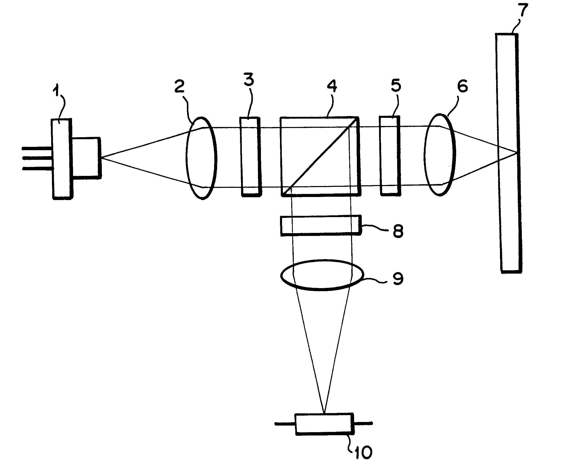
FIG. 8 shows the optical information recording / playback apparatus according to the first embodiment of the present invention. In the present embodiment, a calculation circuit 79 and a driving circuit 80 as the optical information recording / playback apparatus are added to the optical head apparatus according to the first embodiment of the present invention shown in FIG. 1. Conventional optical information recording / playback apparatus are provided with a driving circuit for rotating a disc, a reading signal processing circuit for reading data, an image signal, a sound signal and the like from a disc, a writing signal processing circuit for writing data, an image signal, a sound signal and the like into a disc, a processing circuit such as an operation panel, a control circuit such as CPU and the like, but since they are conventional circuits, the description thereof is omitted.

The calculation circuit 79 calculates a radial tilt si...

second embodiment

of Optical Head Apparatus

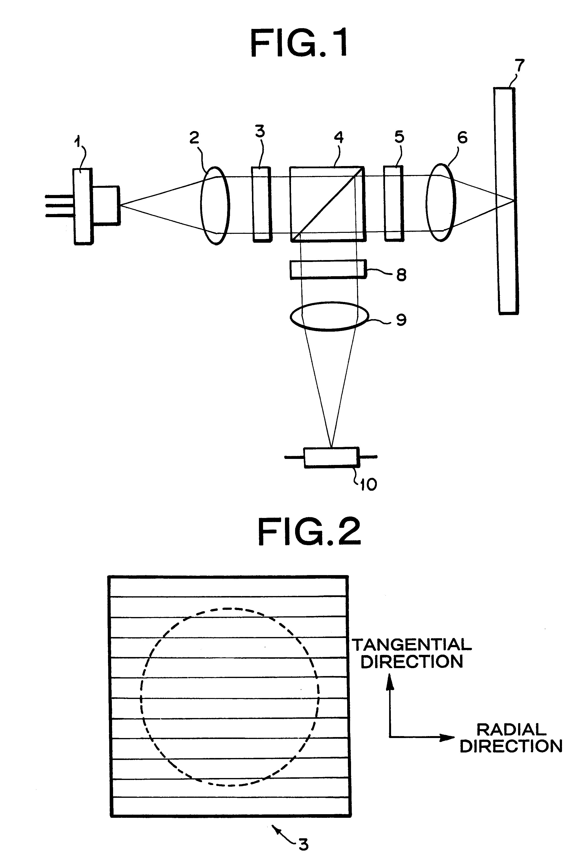
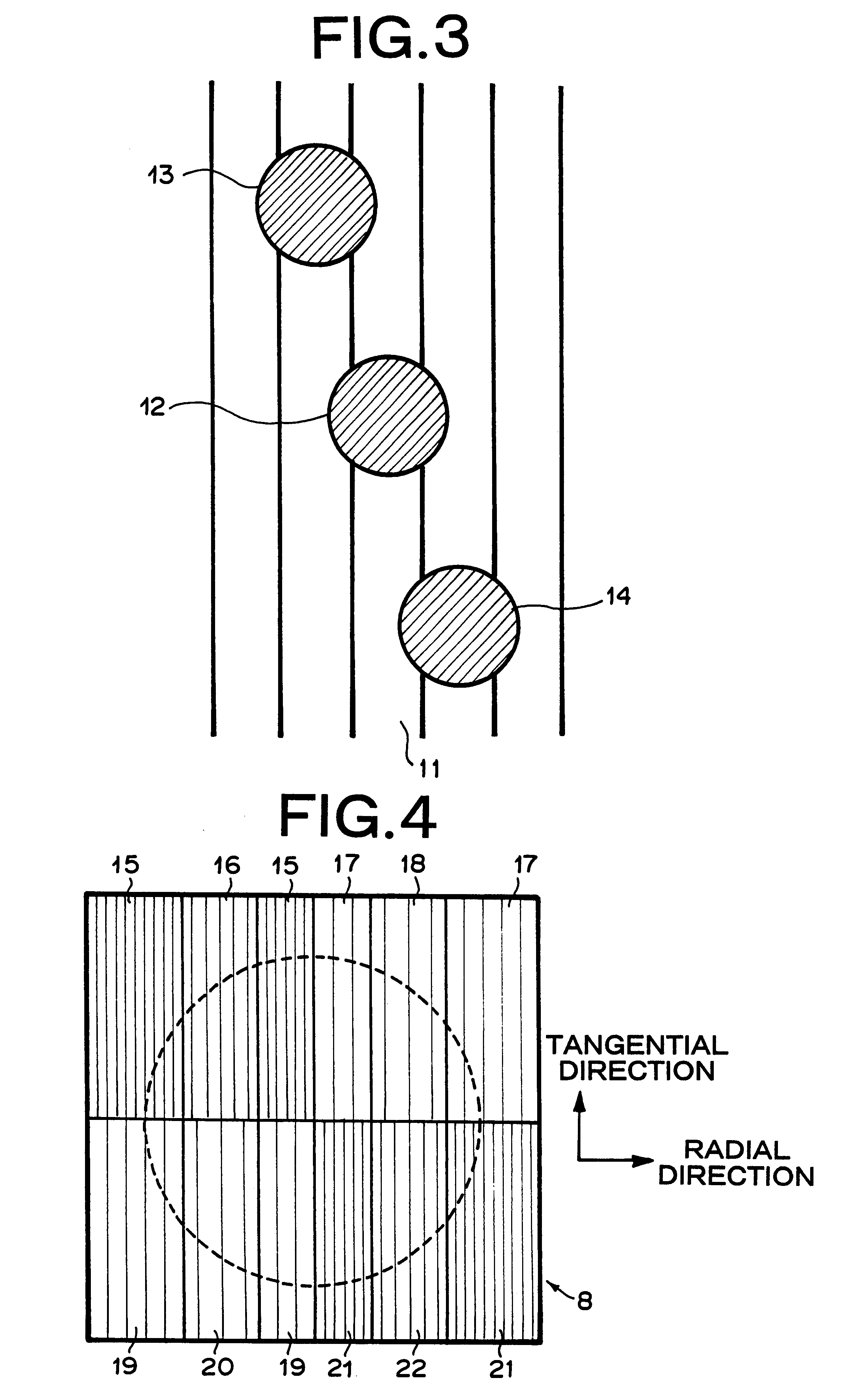
In the second embodiment of the optical head of the present invention, the arrangement of the focused spots on the disc 7 shown in FIG. 3 in the optical head apparatus according to the first embodiment of the present invention is changed into an arrangement of the focused spots on the disc 7 shown in FIG. 10. Spots 12, 82 and 83 correspond to a 0th order beam, a +1st order beam and a -1st order beam diffracted by the diffractive element 3. The focused spot 12 is arranged on a track 11 (groove or land), the focused spot 82 is arranged on a boundary between the track 11 and a track adjacent to it on the left side (land or groove), and the focused spot 83 is arranged on a boundary between the track 11 and a track adjacent to it on the right side (land or groove).

FIGS. 11A to 11P show various waveforms relating to the tracking error signal and the radial tilt signal. The horizontal axis shows a displacement between the focused spot 12 and a groove when the focus...

third embodiment

of Optical Head Apparatus

In the optical head apparatus according to the third embodiment of the present invention, the diffractive element 3 shown in FIG. 2 in the optical head apparatus according to the first embodiment of the present invention shown in FIG. 1 is replaced by a diffractive element 84 shown in FIG. 12.

FIG. 12 is a plan view showing the diffractive element 84. The diffractive element 84 is constituted so that diffraction gratings are formed in a region including the effective diameter of the objective lens 6 shown by a dotted line in the drawing, and the region is divided into two regions 85 and 86 by a straight line which passes through the optical axis of the incident beam and is parallel with the tangential direction of the disc 7. Directions of the diffraction gratings are parallel with the radial direction of the disc 7 in both the areas 85 and 86, and the pattern of the gratings are linear with equal pitches in both the regions 85 and 86. Phases of the gratings ...


PUM

PropertyMeasurementUnit
wavelengthaaaaaaaaaa
thicknessaaaaaaaaaa

Abstract

An object of the present invention is to provide an optical head apparatus which are capable of detecting correctly a radial tilt of an optical recording medium, without allowing offsets in radial tilt signals, even when an objective lens is shifted in a radial direction. A beam emitted from a semiconductor laser is divided into 0th order main beam and ±1st order sub beams. The three beams are shifted in the radial direction of the disc. The three beams reflected from the disc are diffracted by a holographic element, and are received by a photo detector. With respect to the main beam and the sub beams, a radial tilt of the disc is detected on the basis of a difference between intensities of the main and sub beams diffracted from a plurality of regions of the holographic element.

Description

1. Technical Field of the InventionThe present invention relates to an optical head apparatus and an optical information recording and playback apparatus which record on and play back from an optical recording medium, and particularly relates to an optical head apparatus and an optical information recording / playback apparatus which are capable of detecting a radial tilt of an optical recording medium.2. Description of the Prior ArtA recording density in an optical information recording / playback apparatus is inversely proportional to a square of a diameter of a focused spot formed on an optical recording medium by an optical head apparatus. As the diameter of the focused spot becomes smaller, the recording density becomes higher. The diameter of the focused spot is inversely proportional to a numerical aperture of an objective lens in the optical head apparatus. Further, as the numerical aperture of the objective lens becomes higher, the diameter of the focused spot becomes smaller. ...

Claims


Application Information

Patent Timeline
Patent Type & Authority Patents(United States)
IPC IPC(8): G11B7/125G11B7/007G11B7/135G11B7/095G11B7/13G11B11/105G11B11/00G11B7/131G11B7/1353G11B7/1365G11B7/1369G11B7/1381G11B7/1392
CPCG11B7/00718G11B7/0956G11B7/131G11B7/1353G11B7/1365G11B7/1369G11B7/1381G11B7/13927G11B11/10576
Inventor KATAYAMA, RYUICHI
Owner NEC CORP
Why Eureka
Try Eureka