
Quick insertion and removal fastener

Inactive Publication Date: 2004-03-30
HONEYBEE ROBOTICS
View PDF6 Cites 72 Cited by
  • Summary
  • Abstract
  • Description
  • Claims
  • Application Information

AI Technical Summary

Benefits of technology

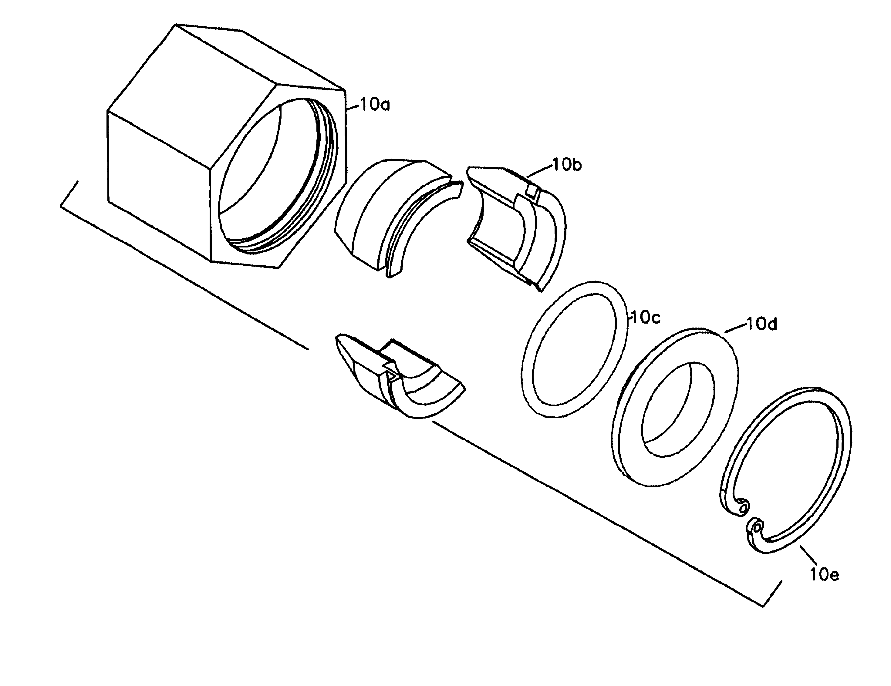
A principal object of the present invention is to provide a quick insertion fastener with an improved configuration of shell assembly that allows quick insertion of a threaded member and tightening (preloading) with a small number of turns, while also ensuring a distributed contact between the shell assembly and the nut casing to increase the strength of the fastener assembly. The shell assembly is designed to perform its function effectively while avoiding the need for multiple parts, multiple springs, and a complex assembly. A further object of the invention is to also provide a means for quick removal of the fastener.
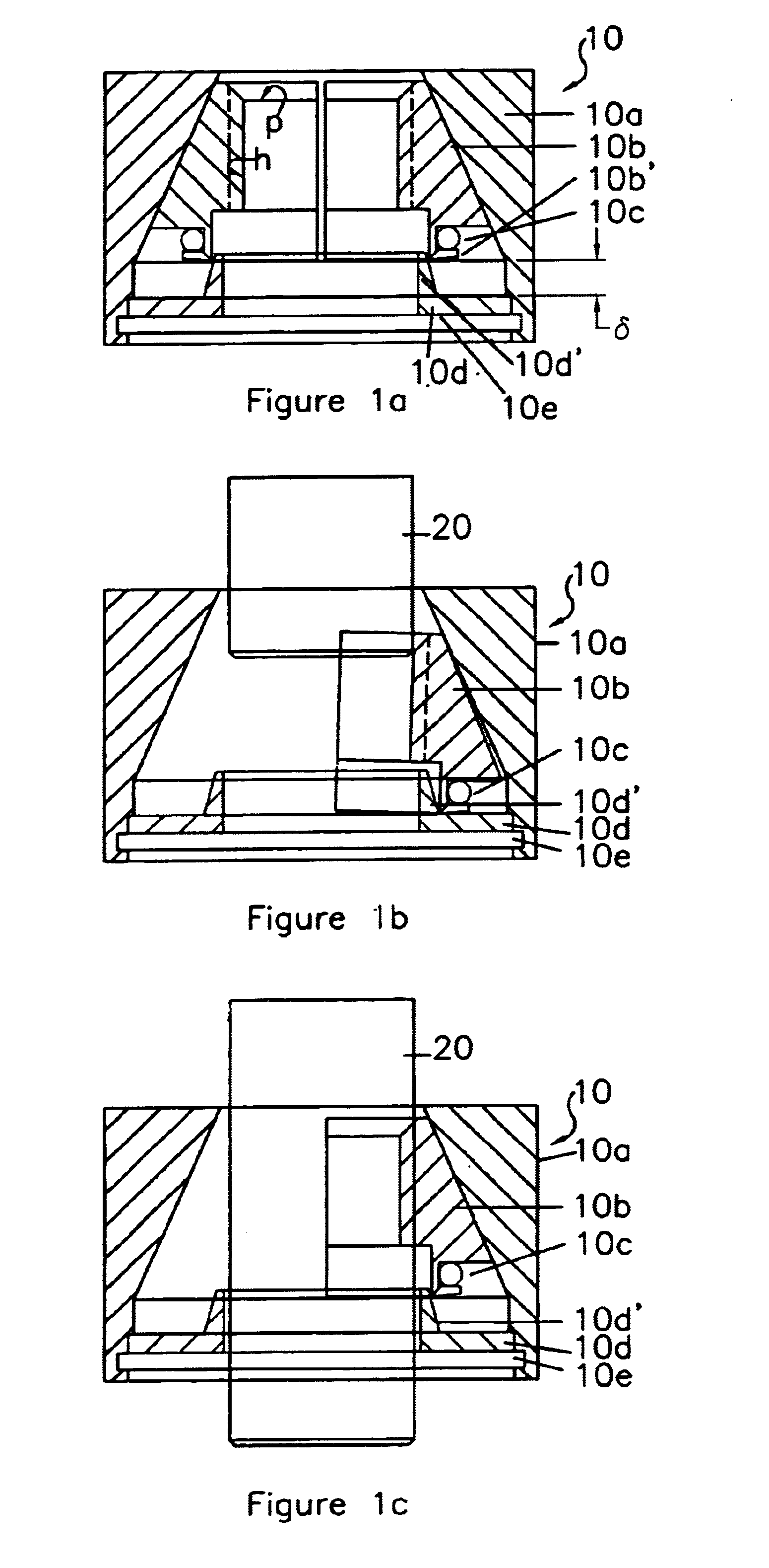
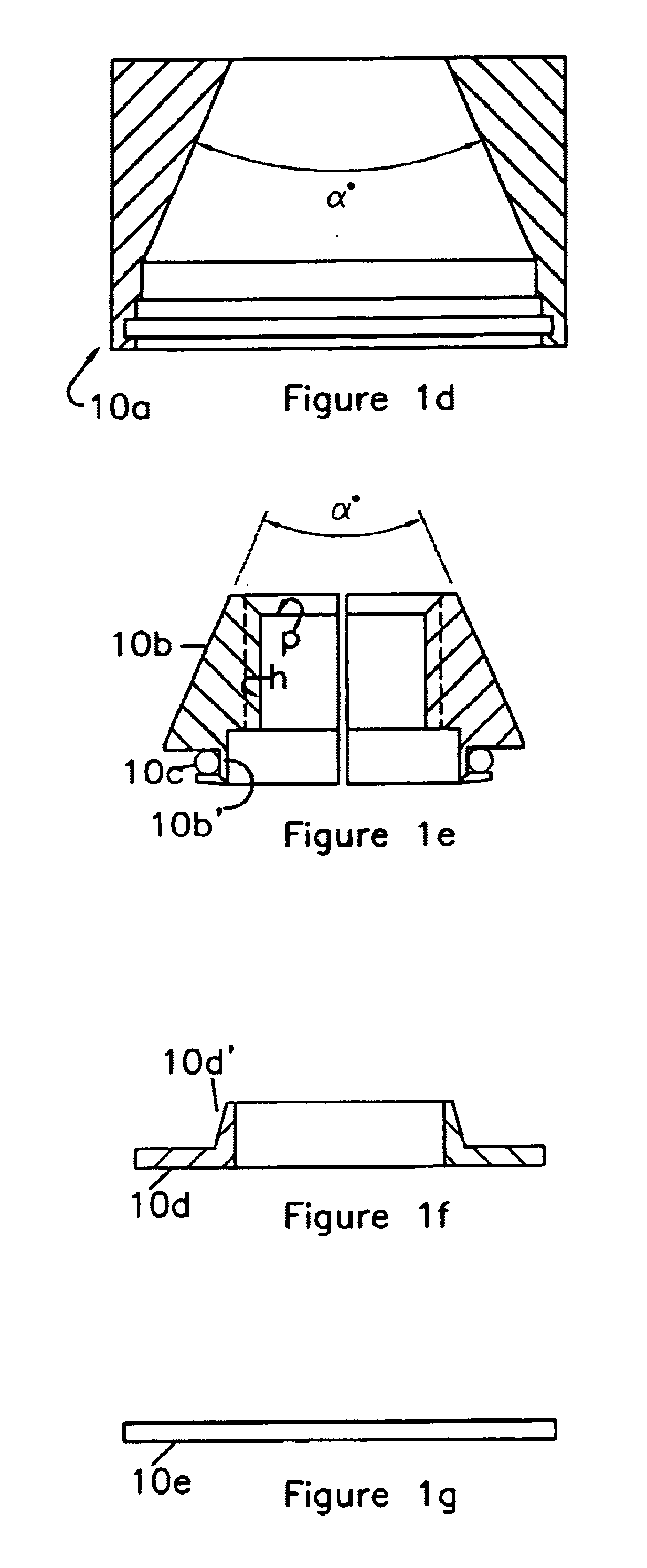
The shell assembly is configured such that when the second member (e.g., a bolt) is inserted with an insertion force into the front part of the first member (e.g., a nut), the shell assembly is displaced axially toward the rear part of the nut casing by a distance ".delta." which is equal to h / tan(.alpha. / 2), and the shell segments are moved apart radially by a distance "h" against the elastic force of the spring by the taper of the end retainer. This allows the internal threads of the shells to clear the thread height "h" and allow the external threads of the bolt to be inserted past the internal threads of the shell segments without interference. When the insertion force of the bolt is released, the spring member urges the shell segments together, and the internal threads of the shell assembly become engaged with the external threads of the bolt, so that the nut can now be tightened with a small number of turns on the bolt.
In other embodiments, the spring member may be formed integrally with the end retainer. For example, it may be a wave compression spring, a segmented spring, circumferential or axial leaf springs, or a flexure spring attached to the end retainer. The shell segments, spring member and end retainer may also be configured to cooperate with an external sleeve member for pulling the shell assembly back relative to the nut casing for quick disengagement from the fastener. Radial, axial, or flat surfaced key elements may also be provided between the nut casing and the shell segments to prevent relative rotation between the parts when the fastener is subjected to preloading forces.

Problems solved by technology

This means that the forces on the threads of the shells, after the system is preloaded, have a weaker load path to ground (or the casing) which reduces the strength of the fastener assembly.

Method used


Image

  • Quick insertion and removal fastener
  • Quick insertion and removal fastener
  • Quick insertion and removal fastener

Examples


Embodiment Construction

In accordance with the present invention, a quick insertion fastener is formed with an internally threaded first member and an externally threaded second member that is inserted in or applied to the internally threaded first member. In the following example, a common type of fastener is described in which the internally threaded member is referred to as a "nut", and the externally threaded member is referred to as a "bolt". However, it is to be understood that the pprinciples of the invention may equally be applied to other types of fastener combinations, such as threaded screw and screw part, threaded rod and rod coupling, etc.

Referring to FIGS. 1a, 1b, and 1c, an exemplary embodiment of a quick insertion fastener is shown having a nut 10 formed by an outer nut casing 10a having an internal tapered surface in a frusto-conical shape of a taper angle ".alpha.", a plurality of shell segments 10b retained within the nut casing, each similarly shaped with an external surface tapered in ...


PUM


Abstract

A quick insertion fastener has an internally threaded first member ("nut") adapted to be quickly attached and tightened on an externally threaded second member ("bolt"). The nut is formed with a casing with an internal frusto-conical front surface, a plurality of threaded shell segments contained in the casing having external frusto-conical front surfaces which abut the front surface of the casing, a spring member positioned at a rear part of the casing which elastically holds the rear ends of the shell assembly together, and an end retainer provided at the rear part of the casing having a taper for engaging the rear ends of the shell assembly and displacing them radially apart when the shell assembly is displaced axially toward the end retainer by insertion of the bolt. This allows the bolt threads to move without interference past the internal threads of the shell segments. When the insertion force of the bolt is released, the spring member urges the shell segments together so that the internal threads of the shell assembly become engaged with the bolt, and the nut can be tightened on the bolt. The spring member may be a radial spring or O-ring, or in the alternatively may be a wave compression spring, segmented spring, circumferential or axial leaf springs, or a flexure spring formed integrally with the end retainer. The nut may also be configured with an external sleeve member for pulling the shell assembly back relative to the nut casing for quick disengagement from the fastener.

Description

This invention generally relates to fasteners, and, particularly, to a nut having an improved structure allowing quick insertion of a threaded bolt and removal thereof.BACKGROUND OF INVENTIONThe prior art has shown various structures for threaded fasteners, such as an internally threaded nut, which may be quickly attached to an externally threaded member such as a bolt, screw or stud, without the time consuming need to rotate the nut a great number of revolutions on the externally threaded member. As illustrated in U.S. Pat. Nos. 3,695,139, 4,378,187, or 5,324,150, fasteners of the quick connecting type generally have an internally threaded nut formed with two or more segments or shells which separate to allow an externally threaded member (bolt) to be pushed into the threads, then close together for tightening over fewer thread pitches on the bolt than would normally be the case with a solid nut. There is typically a frusto-conical surface at the front side (toward the bolt) inside...

Claims


Application Information

Patent Timeline
IPC IPC(8): F16B37/08
CPCF16B37/0857
Inventor ROOPNARINE
Owner HONEYBEE ROBOTICS
Learn More