
System and method for determining fiber orientation in fibrous material webs

a fiber orientation and fiber technology, applied in the direction of material testing goods, geological measurements, instruments, etc., can solve the problems of only one wavelength, high cost, and insufficient orientation of fibers in the machine direction

Inactive Publication Date: 2004-04-06
VOITH PATENT GMBH
View PDF10 Cites 22 Cited by
  • Summary
  • Abstract
  • Description
  • Claims
  • Application Information

AI Technical Summary

Benefits of technology

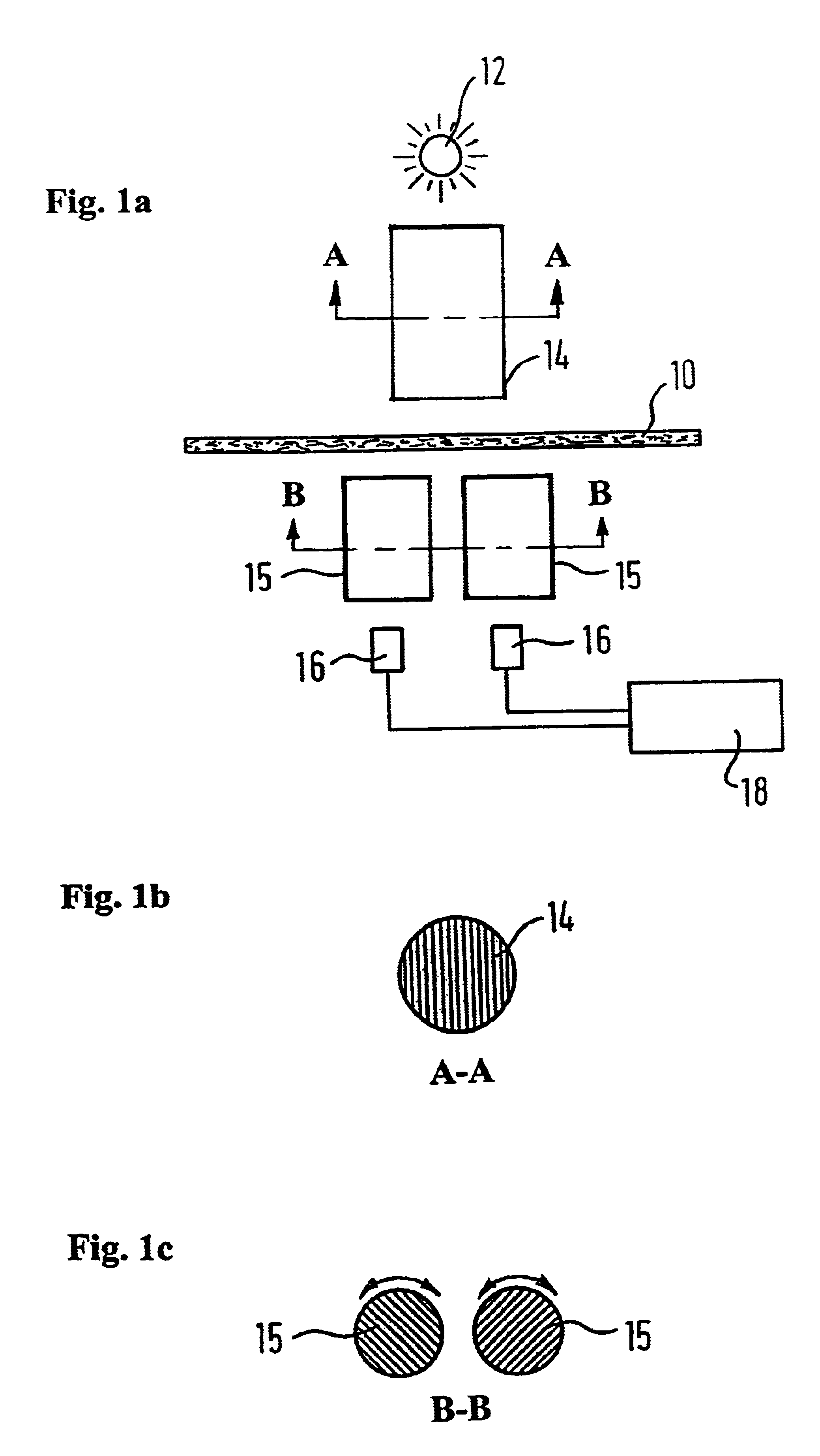
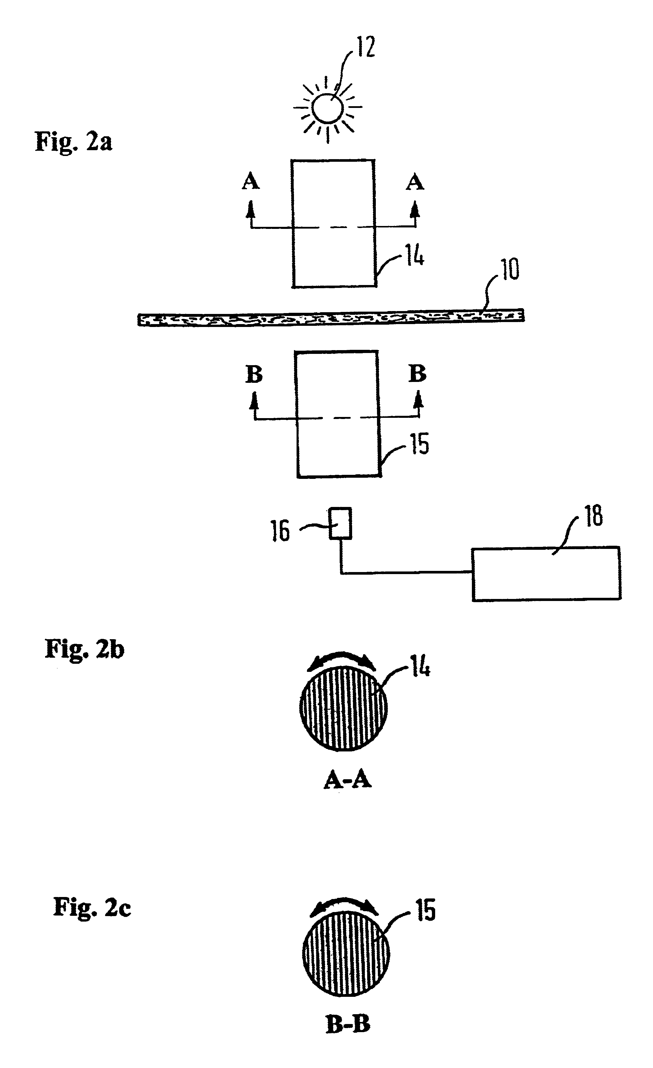
In at least one embodiment of the invention, the optical system includes at least one polarizing filter. With filters of this type, it is possible both to produce linearly polarized radiation and to determine the polarization direction of linearly polarized radiation. Moreover, the use of such a polarizing filter permits the implementation of many different arrangements, all of which are characterized by comparatively simple construction in terms of measurement technology as well as a high degree of measuring precision.
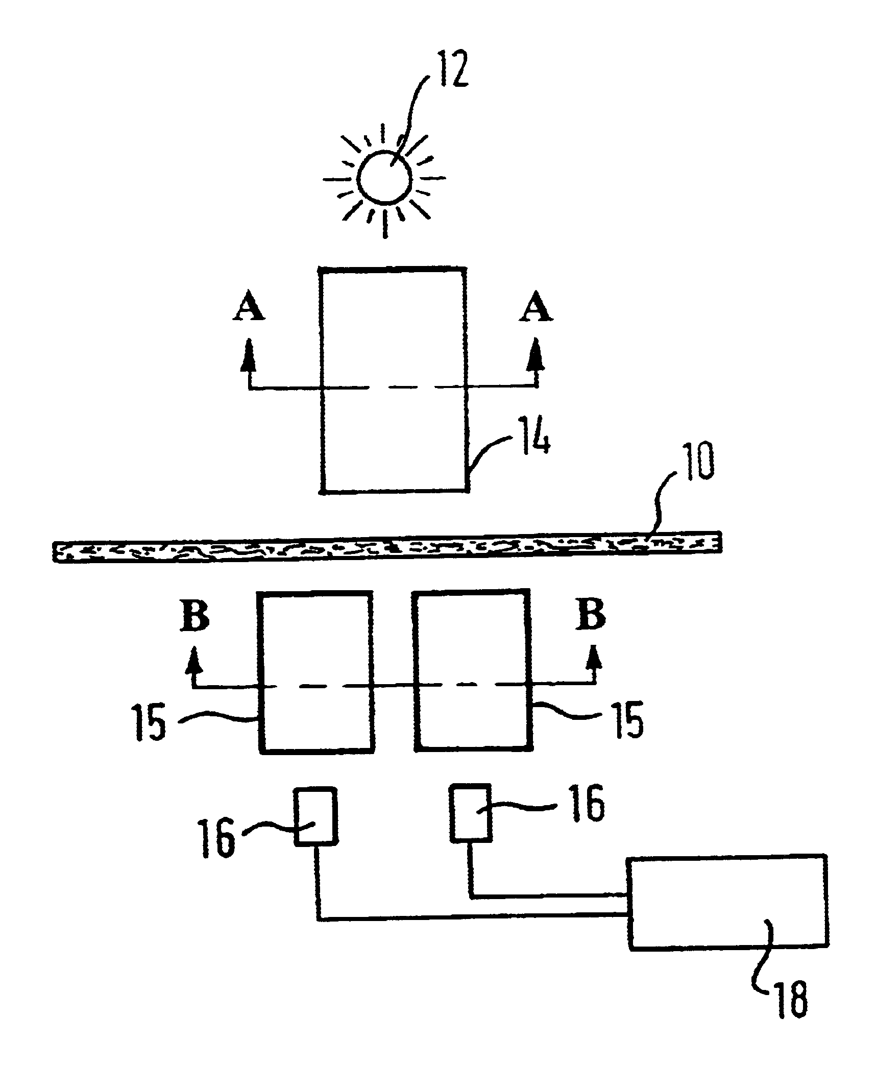
Thus, it is possible to arrange a system having a single optical device in the form of a polarizing filter located between the source and the fibrous material web. The invention provides for the intensity of the linearly polarized radiation, which is produced by the polarizing filter and penetrates the fibrous material web, to be measured by sensor changes as a function of the orientation of the polarizing filter relative to the orientation of the fibers in the fibrous material web. Utilizing this technique, the fiber orientation can be determined in a comparatively simple manner by utilizing repeated measurements of intensity at different orientations of the polarizing filter relative to the fibrous material web. Such a system design can utilize a polarizing filter which is mounted such that it can rotate about an axis running perpendicular to the fibrous material web running direction.

Problems solved by technology

Some disadvantages of this conventional device are its high cost and the fact that it works with only one wavelength.
Otherwise, the fibers are not oriented properly in the machine direction.
Unfortunately, this technique cannot be performed on line as it requires that the paper samples or sections be removed or cut from the web.

Method used


Image

  • System and method for determining fiber orientation in fibrous material webs
  • System and method for determining fiber orientation in fibrous material webs
  • System and method for determining fiber orientation in fibrous material webs

Examples


Embodiment Construction

The particulars shown herein are by way of example and for purposes of illustrative discussion of the embodiments of the present invention only and are presented in the cause of providing what is believed to be the most useful and readily understood description of the principles and conceptual aspects of the present invention. In this regard, no attempt is made to show structural details of the present invention in more detail than is necessary for the fundamental understanding of the present invention, the description taken with the drawings making apparent to those skilled in the art how the several forms of the present invention may be embodied in practice.

FIGS. 1a-c shows an embodiment of a system for determining fiber orientation in a moving paper web 10, whose travel direction is perpendicular to the plane of the drawing. That is, the web is seen from a direction which is transverse to the web running direction so that the web width is clearly seen.

The system according to the ...


PUM

PropertyMeasurementUnit
angleaaaaaaaaaa
angleaaaaaaaaaa
angleaaaaaaaaaa

Abstract

A system and method for determining the orientation of fibers in a fibrous material web. The system includes at least one source of electromagnetic radiation disposed on one side of the fibrous material web, at least one sensor for sensing the electromagnetic radiation emitted by the at least one source disposed on another side of the fibrous material web, and at least one optical device disposed between the at least one source and the at least one sensor, wherein the electromagnetic radiation travels through the at least one optical device and the fibrous material web such that the at least one optical device influences a propagation of the electromagnetic radiation as a function of its polarization properties. The method includes exposing a first side of the fibrous material web to electromagnetic radiation from at least one source, allowing the electromagnetic radiation to penetrate to a second side of the fibrous material web, influencing a propagation of the electromagnetic radiation as a function of its polarization properties with at least one optical device disposed between the at least one source and at least one sensor, and sensing the electromagnetic radiation on the second side with the at least one sensor.

Description

1. Field of the InventionThe invention relates to a system and a method for determining the orientation of fibers in fibrous material webs, particularly paper webs.2. Discussion of Background InformationThe article "High-Resolution Fibre Orientation and Basis Weight Measurement" by B. Drouin et al. in the Journal of Pulp and Paper Science, Vol. 22, No. 7, Jul. 7, 1996 mentions an instrument with which the fiber orientation in paper is measured by a transmission measurement with a rotating plane of polarization. The instrument is based on filtered black body radiation in the far infrared region (FIR) of the electromagnetic spectrum. Some disadvantages of this conventional device are its high cost and the fact that it works with only one wavelength.The invention provides for a system and a method of the type initially described, in which the fiber orientation can be determined more efficiently and with high precision.The invention utilizes at least one source of electromagnetic radiat...

Claims


Application Information

Patent Timeline
Patent Type & Authority Patents(United States)
IPC IPC(8): G01N33/36G01N21/88G01N21/89G01N21/21G01N21/896
CPCG01N21/8914G01N33/367G01N21/21G01N21/896G01N2021/8917
Inventor MUNCH, RUDOLF
Owner VOITH PATENT GMBH
Learn More