Thrombectomy catheter and system

a catheter and thrombosis technology, applied in the field of thrombosis catheters and systems, can solve the problems of reducing the ability of catheters to exhaust the macerated thrombosis material, the inability to remove organized, wall-adherent thrombosis from large vessels,

Inactive Publication Date: 2004-04-13
MEDRAD INC.
View PDF7 Cites 33 Cited by
  • Summary
  • Abstract
  • Description
  • Claims
  • Application Information

AI Technical Summary

Benefits of technology

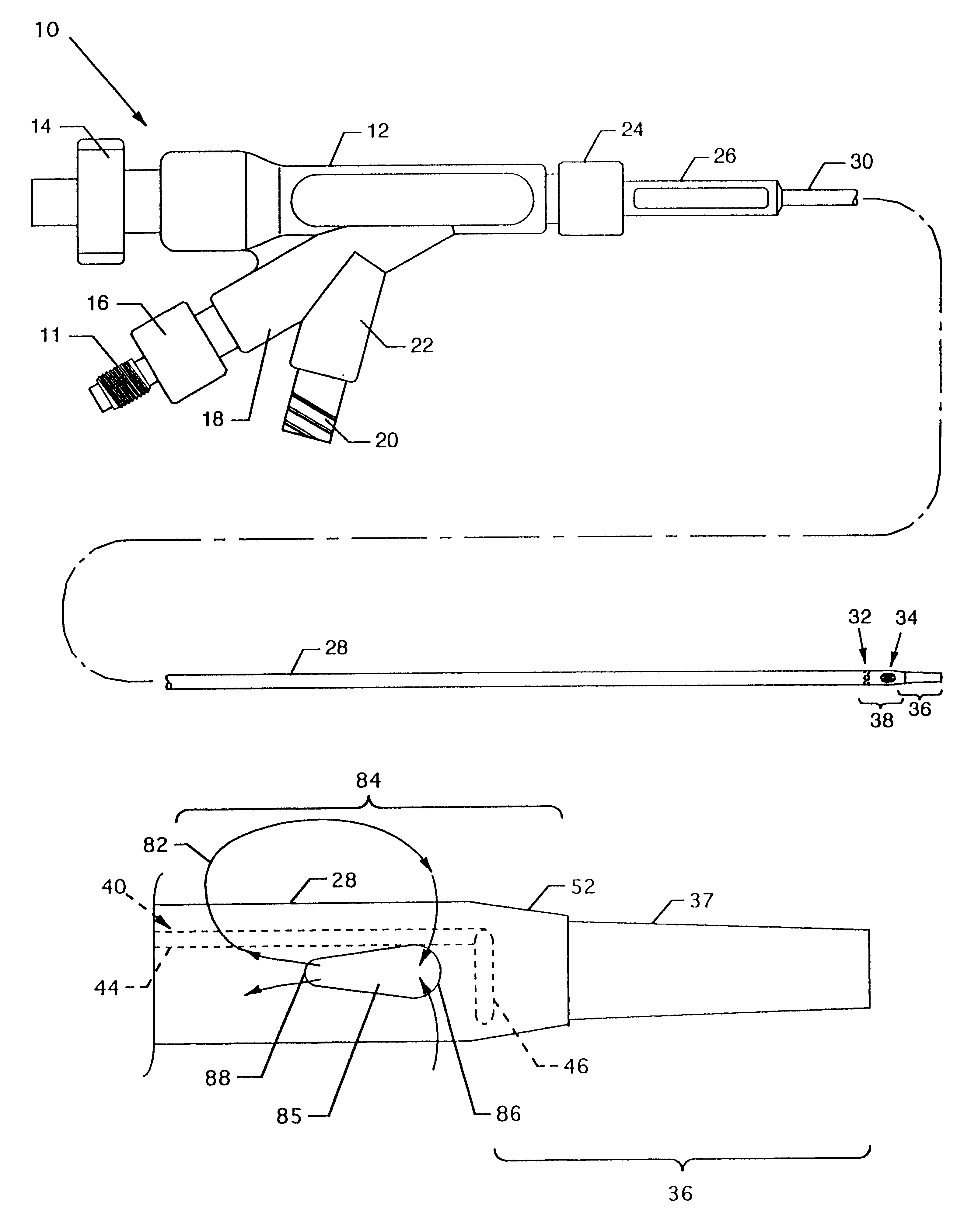
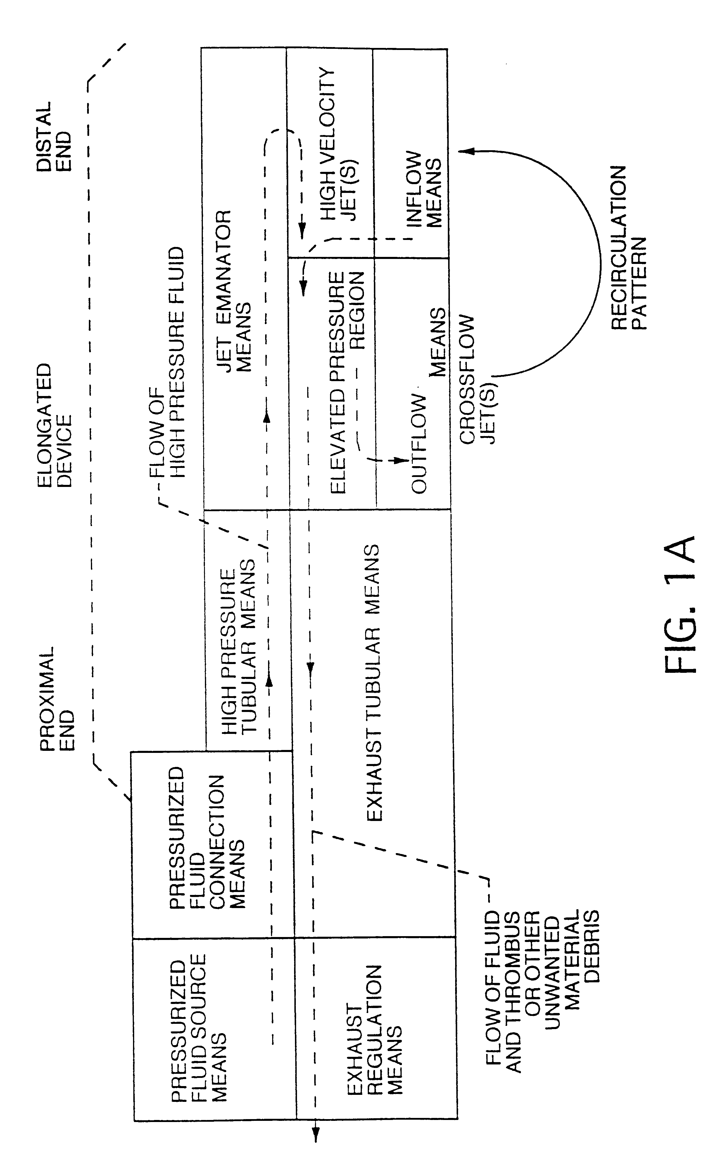
The catheter described herein is provided with outflow means and inflow means and is designed to optimize the drag force on the surface of the vessel by synergistically utilizing inflows and outflows at the catheter tip to create a recirculation pattern. Since the blood vessel can be considered as an open system, the geometric arrangement of the outflow means and inflow means is critical to the maximization of the drag force at the wall of the vessel. Since the catheter is designed to be easily advanced axially through a blood vessel, and axial flows are more likely to dissipate before contributing greatly to recirculation, the flow vectors in the recirculation most important for creating efficient thrombectomy are in the circumferential and radial direction. Radial high velocity flow vectors are created by maximizing the flow through one or more outflow orifices where the one or more outflow orifices are designed to aim the flow perpendicular to the axis of the catheter. Circumferential high velocity flow vectors are created by the demand for entrained fluid by one or more inflow orifices and are supplied substantially from the one or more outflow orifices, with change in fluid flow direction near the vessel wall to return to the catheter.

Problems solved by technology

A limitation of these waterjet thrombectomy catheters has been the inability to remove organized, wall-adherent thrombus from large vessels.
Too small of an area of the outflow orifice(s) will minimize the outflow flow rate and risk plugging of the orifice(s) by macerated thrombotic material, whereas too large of an outflow area will weaken the radial flow vector of the outflow and may reduce the ability of the catheter to exhaust the macerated thrombotic material by allowing the internal pressure at the tip to be reduced to the point that there is no driving force for the exhaust.

Method used


Image

  • Thrombectomy catheter and system
  • Thrombectomy catheter and system
  • Thrombectomy catheter and system

Examples


Embodiment Construction

FIG. 5 illustrates in cross section a mode of operation view of the cross stream thrombectomy catheter 10 with particular attention to the distal end 38 of the exhaust tube 28 positioned in a blood vessel 76, artery or the like at the site of a thrombotic deposit or lesion 78. High velocity jets 80 of saline (or other suitable fluid) are shown being emitted in a proximal direction from the toroidal loop jet emanator 46. The semi-toroidal loop jet emanator 62 of FIG. 4b, L-shaped jet emanator 68 of FIG. 4c, the J-shaped jet emanator 72 of FIG. 4d, the J-shaped jet emanator 75 of FIG. 4e, the J-shaped jet emanator 81 of FIG. 4f, or the J-shaped emanator 91 of FIG. 4g can be incorporated at the distal portion of the jet body 40, as well as and as an alternative to the toroidal loop jet emanator 46 illustrated in this figure, to emanate or emit one or more high velocity jets 80 distally along or near the longitudinal axis of the jet body 40 and the exhaust tube 28. The saline fluid of j...


PUM


Abstract

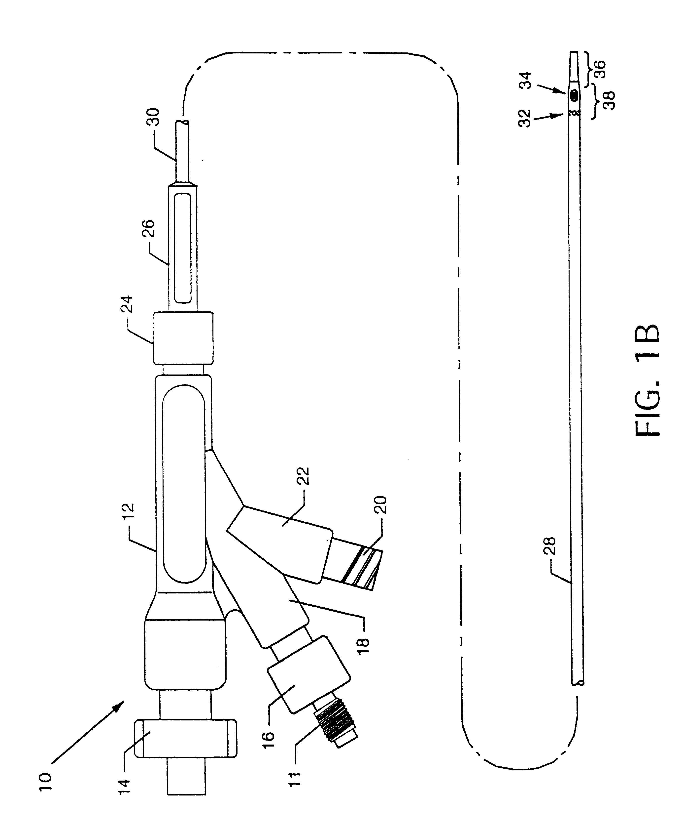
Cross stream thrombectomy catheter and system for fragmentation and removal of thrombus or other material from blood vessels or other body cavities. High velocity saline jets emitted from a toroidal loop jet emanator or other jet emanator in a catheter distal end entrain fluid through inflow orifices, and with flow resistances create a back-pressure which drives cross stream streams through outflow orifices in a radial direction and thence radially and circumferentially to apply normal and drag forces on thrombotic deposits or lesions in the blood vessel or other body cavity, thereby breaking apart and transporting thrombus particles to be entrained through the inflow orifices, whereupon the high velocity jets macerate the thrombus particles which then transit an exhaust lumen or recirculate again via the outflow orifices.

Description

1. Field of the InventionThe present invention relates to apparatus for use in treatment of the human body. More particularly, the present invention relates to an elongated device which may be a single catheter assembly or a multiple component catheter assembly and which is suitable for use through percutaneous or other access, for endoscopic procedures, or for intraoperative use in either open or limited access surgical procedures. Still more particularly, the present invention relates to an elongated device in the form of a waterjet thrombectomy catheter, hereinafter termed cross stream thrombectomy catheter, for fragmentation and removal of thrombus or other unwanted material from blood vessels or body cavities that uses high velocity saline (or other suitable fluid) jets to macerate the thrombus or other unwanted material. The elongated device bears certain similarities to known waterjet thrombectomy catheter constructions but differs therefrom in several material respects, a ma...

Claims


Application Information

Patent Timeline
Patent Type & Authority Patents(United States)
IPC IPC(8): A61B17/22A61M1/00A61B17/32
CPCA61B17/32037A61M1/0084A61B17/3203A61M1/85
Inventor BONNETTE, MICHAEL J.MORRIS, JOHN EDWARDWIESEL, STEVEN E.BRIDGEMAN, JOHN B.KOZAK, DEBRA M.BEAUPRE, ROSEMARY C.JENSON, MARK L.SETUM, CINDY M.DUTCHER, ROBERT C.
Owner MEDRAD INC.
Why Eureka
Try Eureka