Device and method for recording data to optical disk using recording pulse with corrected edge position

a technology of optical disk and recording pulse, which is applied in the field of recording information onto an information recording medium, can solve the problems of deteriorating recording and reproducing characteristics, distorted recording marks, and difficult to generate recording pulses by a synchronous circuit using a clock signal

Inactive Publication Date: 2004-04-13
PANASONIC CORP
View PDF9 Cites 58 Cited by
  • Summary
  • Abstract
  • Description
  • Claims
  • Application Information

AI Technical Summary

Problems solved by technology

In other words, there has been a problem in that the recording mark is distorted like a teardrop.
Therefore, it is hard to generate the recording pulse by a synchronous circuit using a clock signal having a one-channel bit cycle.
Therefore, the recording mark cannot be formed correctly so that recording and reproducing characteristics are deteriorated.
In a conventional optical disc recording device, a delay amount for a specific mark length / space length has been fixedly set and there has no means for correcting the positional shift of the recording pulse which is caused by a fluctuation in a source voltage, a temperature or the like.

Method used


Image

  • Device and method for recording data to optical disk using recording pulse with corrected edge position
  • Device and method for recording data to optical disk using recording pulse with corrected edge position
  • Device and method for recording data to optical disk using recording pulse with corrected edge position

Examples


Embodiment Construction

A preferred embodiment of an optical disc device for recording information on an optical disc according to the present invention will be described in detail with reference to the accompanying drawings.

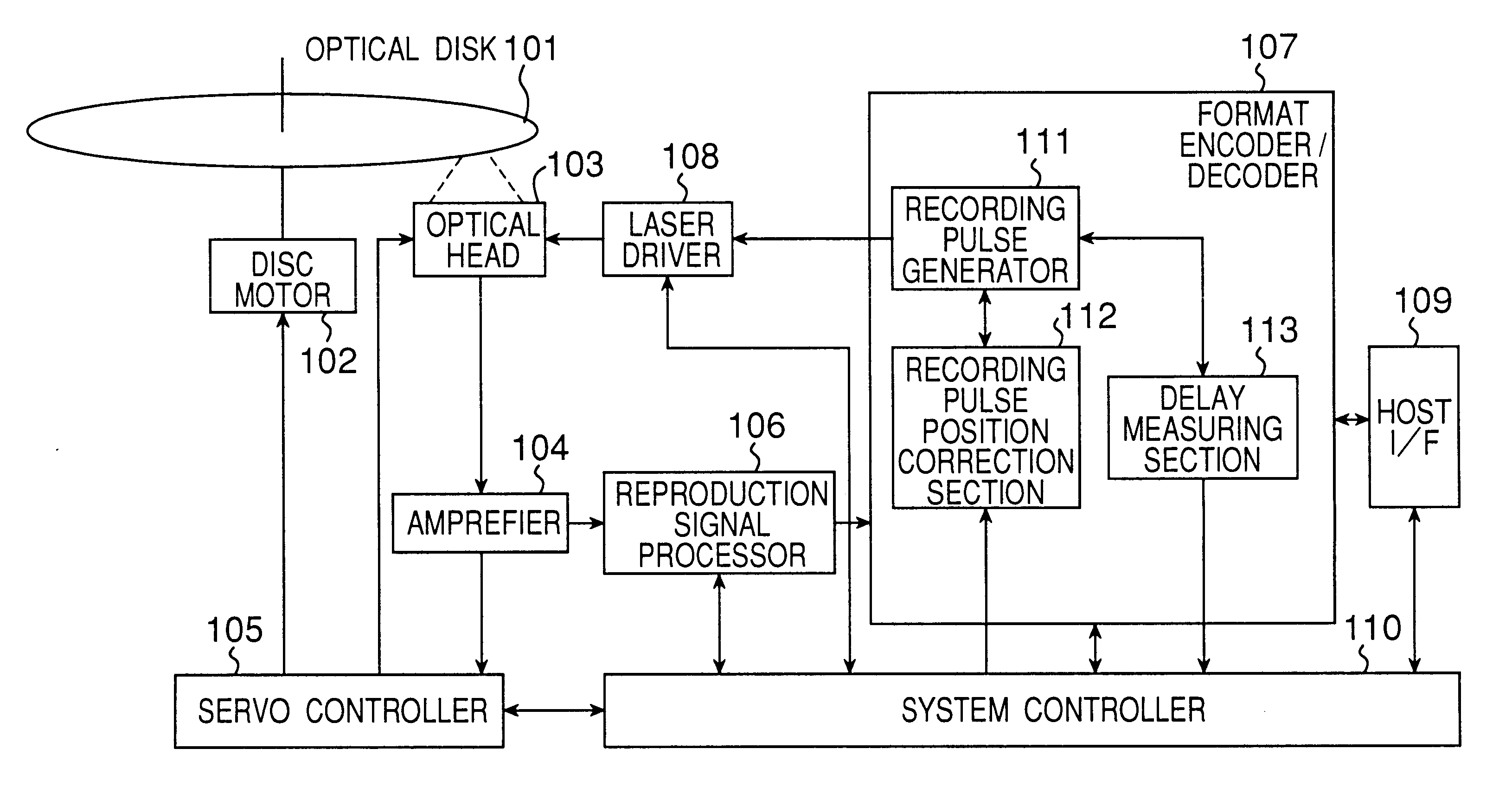
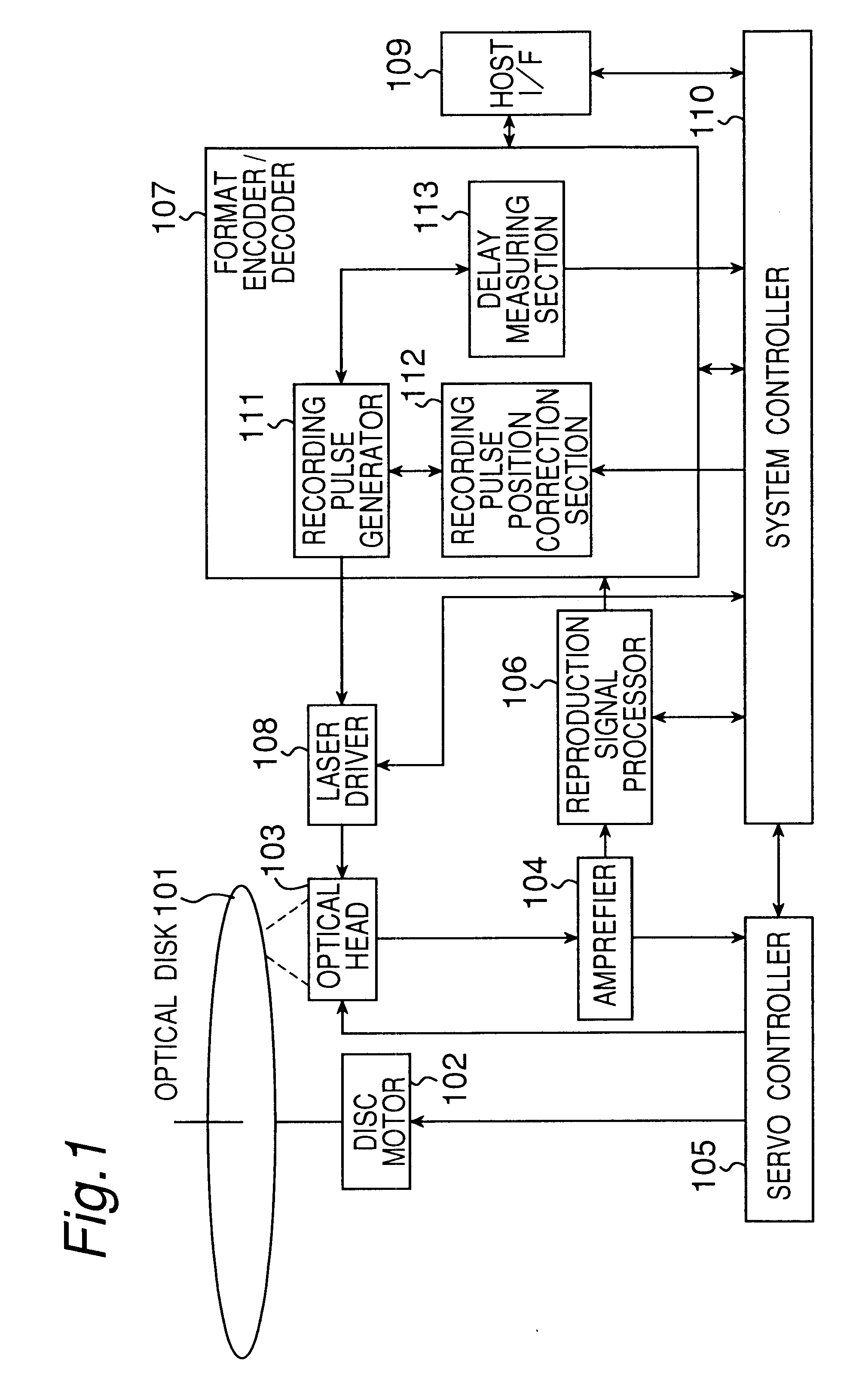
FIG. 1 is a block diagram showing the structure of an optical disc device according to the present invention. In FIG. 1, a disc motor 102 serves to rotate an optical disc 101 at a predetermined number of rotations. An optical head 103 comprises a semiconductor laser, an optical system and a photo detector which are not shown. A laser beam emitted from the semiconductor laser is collected by the optical system and an optical spot is irradiated on the recording face of the optical disc 101, thereby recording and reproducing data. Moreover, light reflected from the recording face is collected by the optical system in the optical head 103 and is then converted into a current by the photo detector, and furthermore, is voltage-converted and amplified by an amplifier 104 and is output as a re...


PUM

PropertyMeasurementUnit
poweraaaaaaaaaa
bit lengthaaaaaaaaaa
space lengthaaaaaaaaaa

Abstract

The present invention provides a device and method for an optical disc such as a DVD which can keep proper edge position of a recording pulse to record data of high quality without depending on a fluctuation in a supply voltage and a fluctuation in a temperature. The optical disc device according to the present invention comprises a laser driver for driving a laser to record data on an optical disc, a recording pulse generator for generating a recording pulse signal by using a predetermined delay circuit, to control the switching of the laser power of the laser driver, a delay amount measuring section for measuring the delay amount of a delay circuit in the recording pulse generator, and a recording pulse position correction section for correcting the predetermined edge position of the recording pulse based on the result of the measurement.

Description

1. Field of the InventionThe present invention relates to a technology for recording information onto an information recording medium such as an optical disc.2. Related ArtIn recent years, attention has been paid to an optical disc such as a DVD-RAM as a large capacity information recording medium, and the optical disc has been developed and merchandised for an external memory of a computer and for picture and voice recording. In general, the optical disc is provided with a spiral or concentric track on a disc surface and laser beams are irradiated along the track, thereby recording and reproducing information. Moreover, the track is further divided into a plurality of sectors which become the minimum unit for recording and reproducing information data.As a method for recording information onto the optical disc, there has generally been known a light modulation recording method for modulating the intensity of a laser beam irradiated on the track onto which data are to be recorded ac...

Claims


Application Information

Patent Timeline
Patent Type & Authority Patents(United States)
IPC IPC(8): G11B5/76G11B5/74G11B7/00G11B7/0045G11B7/006G11B7/125
CPCG11B7/0062G11B7/126G11B7/1263
Inventor GUSHIMA, TOYOJIINOUE, IKUNORI
Owner PANASONIC CORP
Why Eureka
Try Eureka