Recoil starter

a starter and coil technology, applied in the field of coil starters, can solve the problems of relatively high manufacturing cost, and achieve the effects of reducing the number of parts, simplifying the structure of coil starters, and facilitating assembly and attaching of coil starters

Inactive Publication Date: 2004-04-20
STARTING IND CO LTD +1
View PDF3 Cites 14 Cited by
  • Summary
  • Abstract
  • Description
  • Claims
  • Application Information

AI Technical Summary

Benefits of technology

As explained above, since recoiling unidirectional rotating means, which is mounted on the recoil starter of the present invention, is constructed such that the engagement and disengagement between the locking claws and the engaging claws can be executed by moving the movable locking claw member provided with the locking claws in the direction along the rotational axis, a plurality of locking claws are no longer required to be supported in a manner that each of the locking claws is enabled to individually oscillate as seen in the case of the conventional ratchet mechanism provided with oscillating locking claws. Moreover, the movable locking claw member is only required to be urged to move toward the interlocking rotor by making use of a single urging member. The locking claws, therefore, are no longer required to be separately provided with an individual urging member. As a result, it is now possible to reduce the number of parts to be employed, to simplify the structure of the recoil starter, and to easily assemble and attach the recoil starter, thus making it possible to effectively reduce the manufacturing cost thereof.
Furthermore, since buffering / power-accumulating means, which includes, e.g., a spiral spring mechanism, is interposed at a midway of the power transmitting system between the driving member and the driven member, it is possible to minimize fluctuation in the rope-pulling force so as to allow for a smooth rope-pulling operation, thus enabling even a person having weak physical strength to easily start the engine.

Problems solved by technology

As a result, the conventional recoil starter suffers from a drawback in that a large number of parts are required to be employed, its structure is complicated, it requires troublesome assembling and attachment work, and the manufacturing costs are relatively high.

Method used


Image

  • Recoil starter
  • Recoil starter
  • Recoil starter

Examples


Embodiment Construction

The present invention will be further explained with reference to the drawings depicting embodiments of the recoil starter according to the present invention.

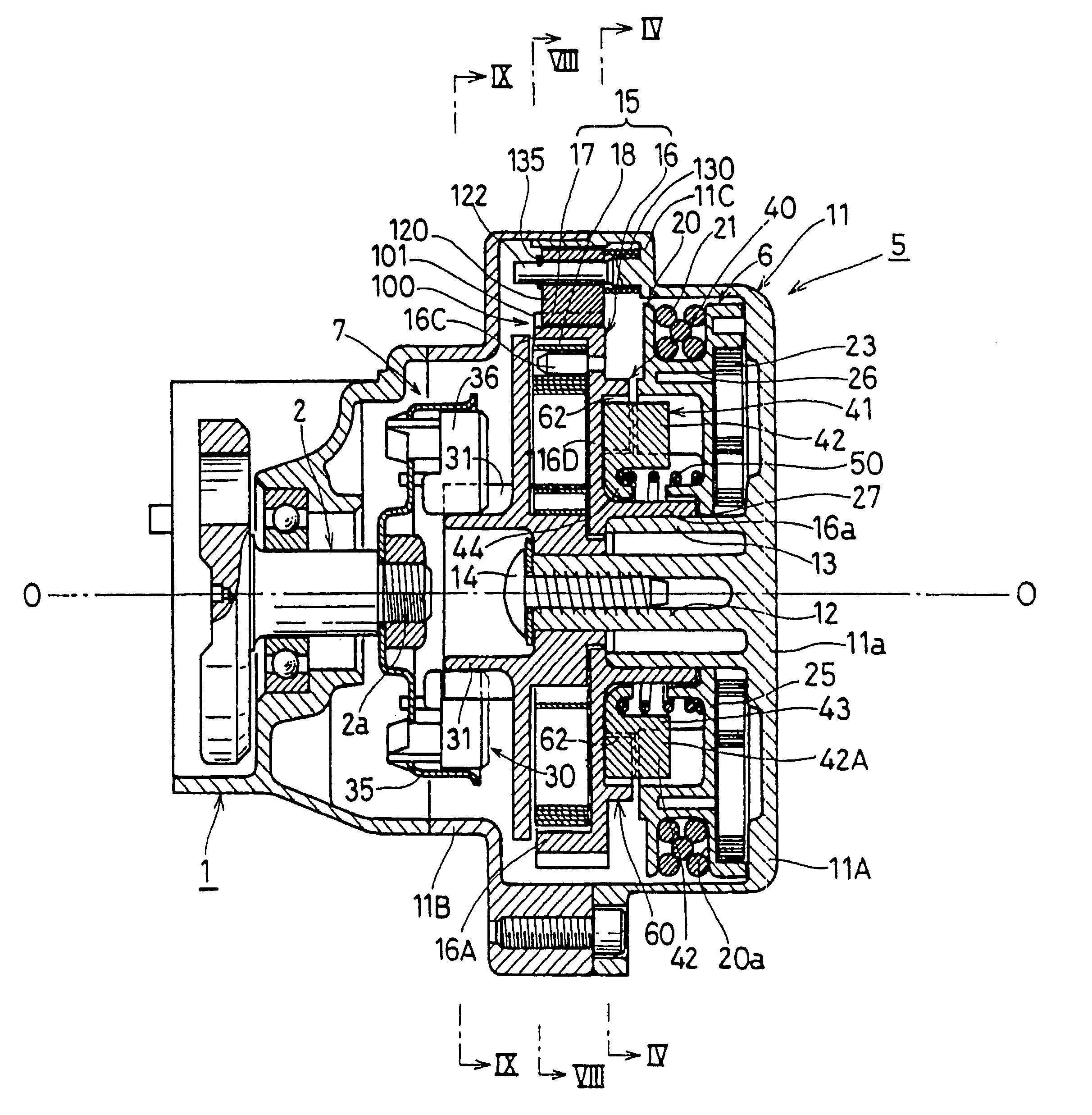
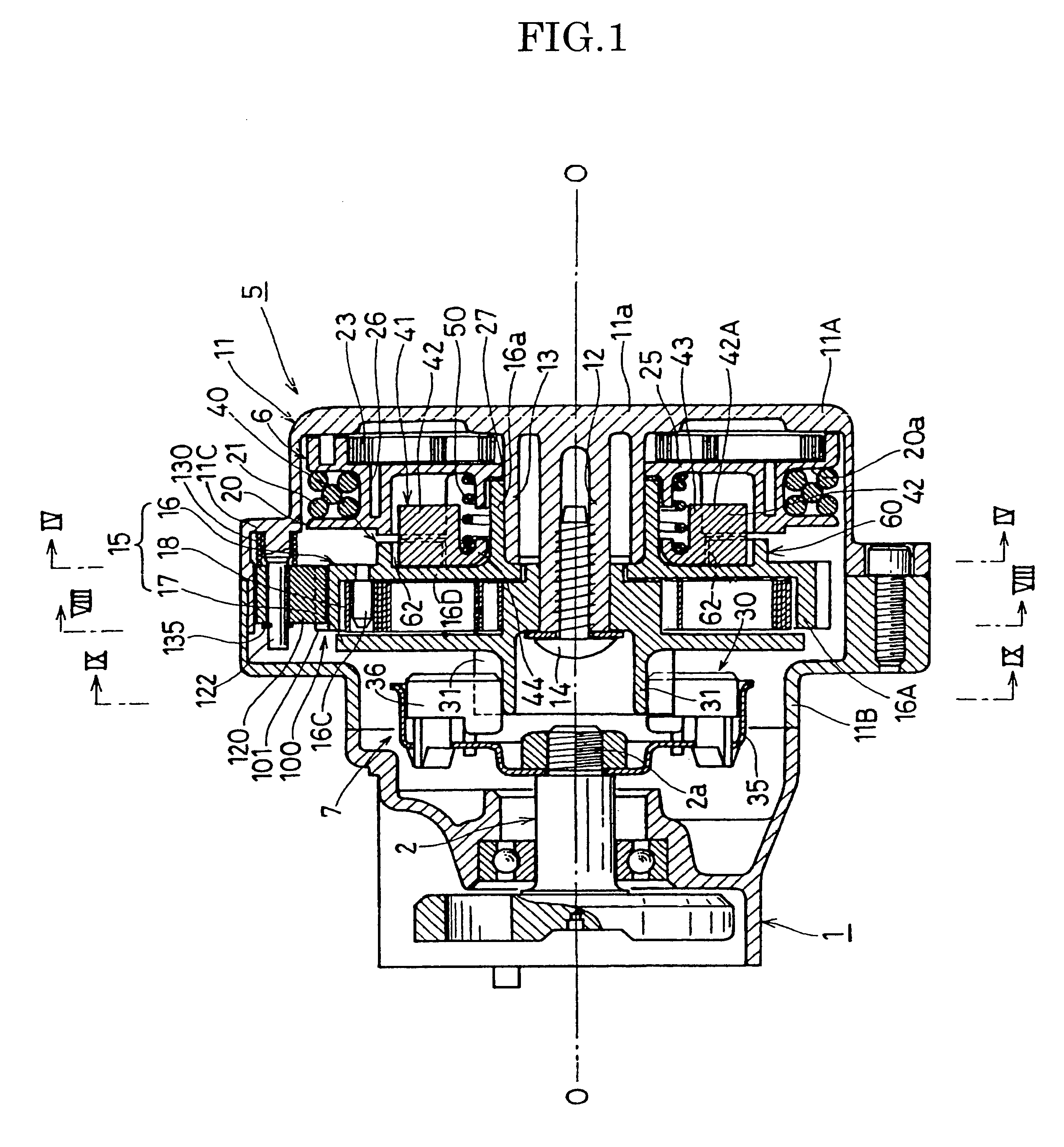
FIG. 1 is a cross-sectional view of a starter representing one embodiment of the recoil starter according to the present invention. Referring to FIG. 1, a recoil starter 5 is designed so as to be disposed close to one end 2a of a crankshaft 2 of an internal combustion engine, such as a small air-cooled internal combustion engine of 23 mL to 50 mL in displacement. The recoil starter 5 includes a starter case 11 which is adapted to be mounted on one sidewall of the engine 1. This starter case 11 includes a two components forming a cylindrical structure. Inside an outer case member 11A of the starter case 11, which is located away from the engine 1, there is disposed a driving member 6 which is adapted to be revolved as a recoil rope 21 is pulled via a recoil handle 22. Inside an inner case member 11B of the starter case 11, which...


PUM


Abstract

A recoil starter having a driving member and a driven member, wherein the driving member further includes recoiling unidirectional rotating means. The recoiling unidirectional rotating means includes a movable locking claw member which is supported by one of the rope reel and the interlocking rotor in such a manner that it is rotatable therewith and movable in a direction along the rotational axis thereof, an urging member for urging the movable locking claw member toward the other of the rope reel and the interlocking rotor, and an engaging member mounted on the other of the rope reel and the interlocking rotor. The unidirectional rotating means is constructed in such a manner that, when the rope reel is rotated in the driving direction, the movable locking claw member is caused to contact and engage with the engaging member to thereby enable the rotation of the rope reel to be transmitted to the interlocking rotor, and that, when the rope reel is rotated reversibly to the driving direction relative to the interlocking rotor, the engagement between the movable locking claw member and the engaging member is released.

Description

The present invention relates to a recoil starter adapted for use in an internal combustion engine, and in particular, to a recoil starter provided with improved unidirectional rotating means for recoiling (which hereinafter will be referred to as recoiling unidirectional rotating means) designed to transmit the rotation of a rope reel to a driven member.DESCRIPTION OF THE RELATED ARTA recoil starter adapted for use in an internal combustion engine is conventionally provided with a driving member having a rope reel, around which a recoil rope is wound, and a driven (idler) unit comprising a centrifugal ratchet mechanism. In order to start the internal combustion engine, the recoil rope (recoil handle) is pulled to revolve the rope reel, and the resulting revolution of the rope reel is transmitted via the driven member to the crankshaft of the internal combustion engine, to thereby start the engine.The driving member also includes, in addition to the aforementioned rope reel, a spira...

Claims


Application Information

Patent Timeline
Patent Type & Authority Patents(United States)
IPC IPC(8): F02N3/00F02N3/02F16D11/00F16D41/22F16H33/02
CPCF02N3/02
Inventor NIEDA, SEIICHIHASHIBA, HIDEKIAIYAMA, FUMIHIKOTAKAHASHI, ISAO
Owner STARTING IND CO LTD
Why Eureka
Try Eureka