

Variable function voting solenoid-operated valve apparatus and testing method therefor
a solenoid-operated valve, variable function technology, applied in the direction of ignition automatic control, electric controllers, instruments, etc., can solve the problems of false initiation of safety action, limited overall safety availability performance of 1 out of 1 solenoid-operated valves, and configurations that can achieve only relatively low plant system reliability, and achieve high diagnostics. high, high safety availability
Inactive Publication Date: 2004-04-20
SIS TECH APPL
View PDF4 Cites 15 Cited by
- Summary
- Abstract
- Description
- Claims
- Application Information
AI Technical Summary
Benefits of technology
This configuration maintains high safety availability and plant system reliability by enabling testing and maintenance without bypassing the system, reducing operational downtime, and providing diagnostic information to ensure safety actions are executed correctly.
Problems solved by technology
However, most prior solenoid valve configurations have necessarily required a trade-off by operators between either discontinuing safety monitoring during testing and maintenance or risking false initiations of the safety action as a result of limited or incomplete testing and maintenance.
In practice, the overall safety availability performance of a 1 out of 1 solenoid-operated valve is therefore limited by the percentage of operational time required in a bypass state for testing and maintenance.
Moreover, such configurations can achieve only relatively low plant system reliability outside of testing and routine maintenance, since an unexpected component failure within the solenoid-operated valve, for example, a coil failure, will necessarily cause an inadvertent venting or isolation of the fluid or pneumatic supply, i.e., actuation of the process valve and initiation of the safety action.
Accordingly, the device is incapable of actuating te process valve, and of isolating or venting the process fluid supply in response to an unsafe condition while the system is in bypass mode.
Thus, the safety availability performance of the 1 out of 2 solenoid is also limited by the percentage of operational time required for bypassing and testing.
Moreover, since there are two discrete solenoids capable of initiating the safety action, a failure in a single solenoid-operated valve coil can lead to the inadvertent actuation of the process valve and isolation or venting of the process fluid.
However, since the likelihood of individual component failure within the solenoid-operated valve system is effectively doubled (for example, both solenoid-operated valves must always function properly), the configuration suffers from relatively low safety availability unless function-tested very frequently.
The testing and maintenance cycle is generally time and manpower intensive since most of the known 2 out of 2 configurations are still tested manually.
As with the previously discussed solenoid-operated valve systems, therefore, the safety availability performance of the device is limited by the percentage of operational time required during bypassing and testing or maintenance.
In practice, however, those of skill in the pertinent arts have found that the use of three solenoid-operated valves substantially increases the overall price of the system.
Moreover, additional logic control system input and output points are required relative to simpler configurations, and thus installation and operating expenses are also increased.
In short, the high costs associated with the 2 out of 3 solenoid configuration have virtually negated its effective industrial utility.
However, the use of four solenoid-operated valves in a voting configuration has been found to require an unusually large amount of space to accommodate its complex pneumatic tubing, and such complexity obviously increases the associated capital and installation costs.
Perhaps even more importantly, many commercial operators of voting solenoid-operated valve systems have been found to particularly disfavor the complex quad-voting configuration because of the elevated potential for testing and maintenance error associated therewith.
The use of dual solenoid-operated valve configurations (generally a combination of 1 out of 2 and 2 out of 2 operational modes) is well known by those of skill in the pertinent arts, but the technical trade-off between high safety availability (in the 1 out of 2 mode) and high plant system reliability (in the 2 out of 2 mode) remains unacceptably problematic.
Method used
View moreImage
Smart ImageViewing Examples

Examples
Embodiment Construction
is intended primarily for illustrative purposes, and is not intended to include all possible aspects of the present invention. Moreover, while the invention has been shown and described with respect to an exemplary embodiment, those of skill in the pertinent arts should appreciate that the foregoing detailed description, and various other modifications, omissions and additions, so long as in the general form and detail thereof, may be made without departing from either the spirit or scope of the present invention. Having thus described the invention,
Login to View More PUM
 Abstract
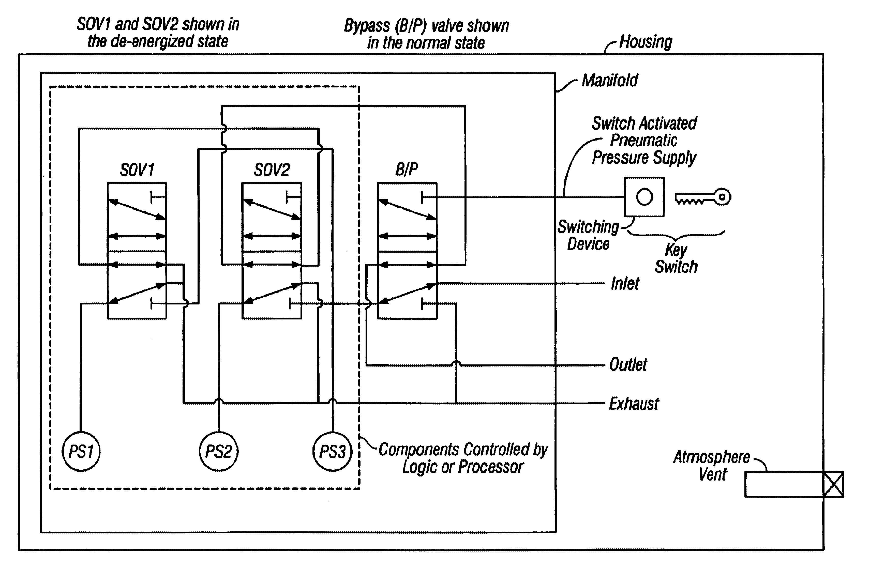
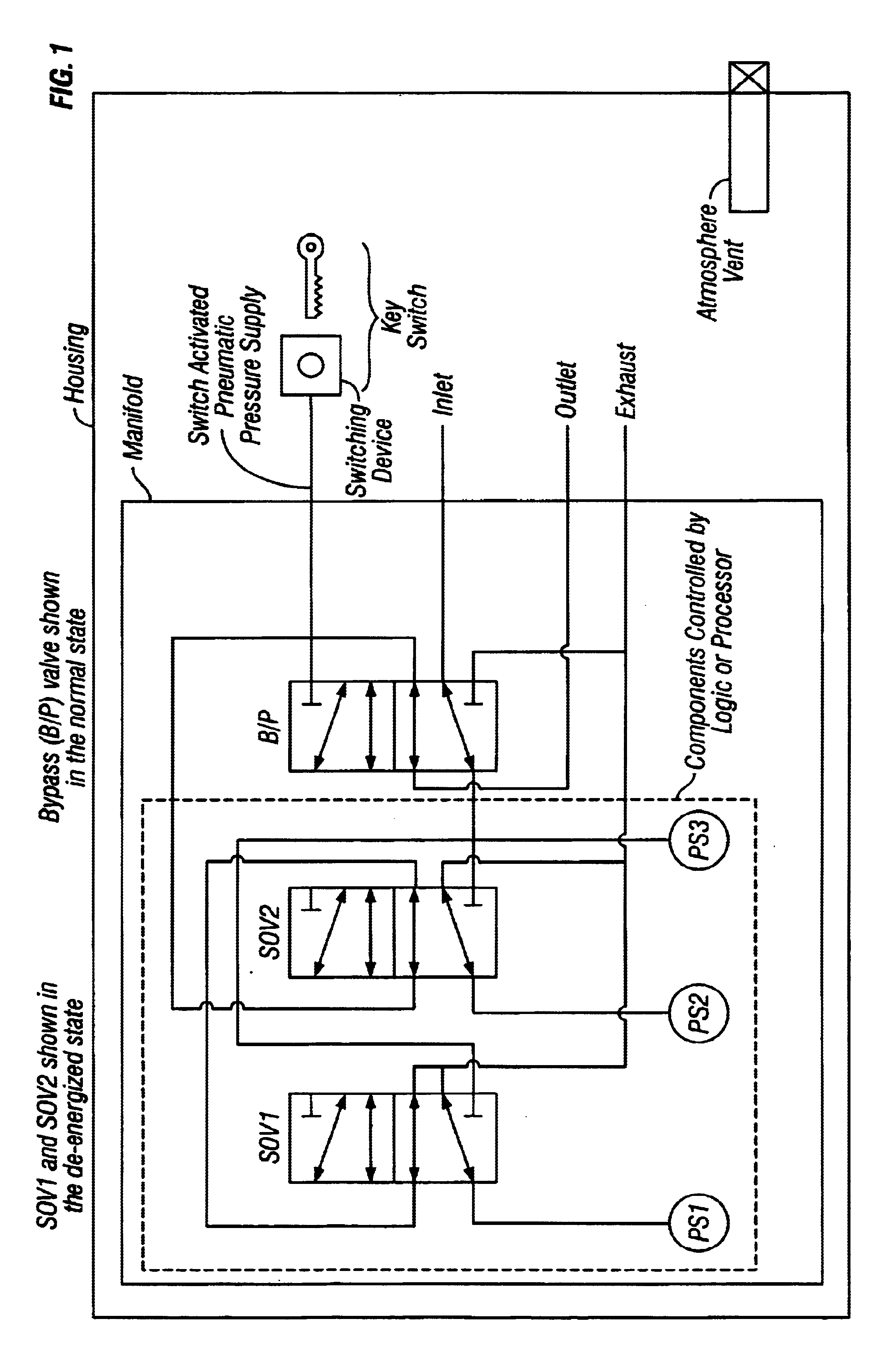
A variable function voting solenoid-operated valve apparatus is provided having both high safety availability and high plant reliability that does not require a plant system to be bypassed during testing. Also provided is a variable function voting solenoid-operated valve apparatus wherein initiation of a safety action will occur only if each of a pair of operatively associated solenoid-operated valves in the apparatus are actuated, and wherein either of the solenoid valves can singly default to a pre-designated safety action without inadvertently actuating the process valve and isolating or venting the process fluid. Also provided is a variable function voting solenoid-operated valve apparatus wherein either a "1 out of 1 with hot stand-by" operational mode or a "2 out of 2 with high diagnostics" operational mode may be selected by an operator using a logic control system depending on the technical requirements of a given plant environment. Also provided is a variable function voting solenoid-operated valve apparatus, wherein a plurality of pressure sensing devices are incorporated to detect failure of either of a pair of operatively associated solenoid-operated valves so as to prevent inadvertent initiation of a safety action, and wherein a bypass switch is provided to allow on-line maintenance of the device should one of the solenoid valves fail during operation or when a failure is detected during a testing cycle. Finally, a variable function voting solenoid-operated valve apparatus is provided, wherein diagnostic information on the performance of the safety action, a partial movement of the process valve can be executed to prove the process valve is capable of actuating to the safe state, can be ascertained with either operational mode using a logic control system depending on the technical requirements of a given plant environment.
Description
Not ApplicableSTATEMENT REGARDING FEDERALLY SPONSORED DEVELOPMENTNot Applicable1. Field of the InventionThe present invention relates generally to voting solenoid-operated valve devices for testing and controlling industrial process systems, and more particularly to a variable function voting solenoid-operated valve apparatus that provides low-cost, high-reliability testing and control of a fluid media processing or manufacturing plant.2. Background of the InventionModern process or manufacturing plants consist of innumerable individual components. These components are integrated to form operational systems controlled by instrumentation and control systems consisting of a variety of sensors and controllers. The operational and control systems serve not only to achieve desired process conditions and parameters, but also to allow a plant facility to safely modify or discontinue operation of all or a portion of the plant's systems and components in order to avoid predetermined deleteri...
Claims
Login to View More Application Information
Patent Timeline
 Patent Type & AuthorityPatents(United States)
IPC IPC(8): G05B9/03
CPCG05B9/03Y10T137/8326Y10T137/0318Y10T137/8359
InventorSUMMERS, ANGELAZACHARY, BRYAN
OwnerSIS TECH APPL