Polarization-OTDR for measuring characteristics of optical fibers

a technology of optical fibers and characteristics, applied in the direction of optical apparatus testing, structural/machine measurement, instruments, etc., can solve the problems of inability to achieve the characteristics of optical fibers that are unacceptable for modern optical communication systems, and inability to achieve the characteristics of optical fibers that are not acceptable to the general publi

Inactive Publication Date: 2004-04-20
EXFO ELECTRO OPTICAL ENG
View PDF6 Cites 65 Cited by
  • Summary
  • Abstract
  • Description
  • Claims
  • Application Information

AI Technical Summary

Problems solved by technology

Optical fibers which have been installed for several years, however, may exhibit levels of PMD that are unacceptable for modern optical communication systems.
It has been found that, in many cases, the unacceptable overall PMD is caused by a short section of the optical fiber cable.
One limitation of Galtarossa's technique is that it derives statistics based upon wavelength and so needs a wavelength tunable source.
Therefore, high-PMD fibers, that necessarily exhibit high birefringence, are more difficult to characterize than low-PMD fibers.
Unfortunately, an important limitation of this technique arises when testing a concatenation of short fibers having very dissimilar birefringence values.
This ambiguity makes reliable interpretation of the DOP signature difficult when a link is made of a concatenation of relatively short fibers sections (for example, 2 km or less).

Method used


Image

  • Polarization-OTDR for measuring characteristics of optical fibers
  • Polarization-OTDR for measuring characteristics of optical fibers
  • Polarization-OTDR for measuring characteristics of optical fibers

Examples


Embodiment Construction

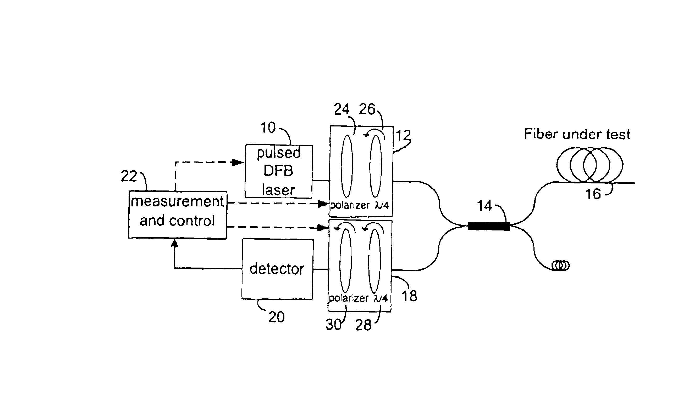
Referring to FIG. 4, a P-OTDR comprises a pulsed optical source 10 for supplying pulses of polarized light and a polarization state adjustment (PSA) means 12 coupled to the source 10 for receiving the light pulses and adjusting their states of polarization successively to each of several different SOPs. A branching device 14, for example a circulator, a three-port coupler or a four-port coupler, couples the pulses from the output of the PSA means 12 to the fiber-under-test (FUT) 16. A polarization analyzer 18 coupled to branching device 14 receives the backscatter signal from the branching device 14, analyzes it and supplies it to a detector 20 which converts it to an electrical signal which it supplies to a measurement and control unit 22. The latter controls the optical source 10, PSA means 12 and analyzer means 18.

Preferably, source 10 is a narrow-linewidth source, such as a distributed feedback laser, to avoid spectral depolarization. Typically, the line width is less than 0.1 n...


PUM

PropertyMeasurementUnit
coupling lengthaaaaaaaaaa

Abstract

In a method of polarization optical time-domain reflectometer (P-OTDR) for measuring a parameter of an optical transmission path, for example an optical fiber, by transmitting pulses of light into the path and measuring the state of polarization of backscattered light against distance, statistical analysis of the degree of polarization (DOP) of the backscattered signal is used to detect sections of an optical transmission path for which mode-coupling behaviour (long h) leads to high PMD. Preferably, successive DOP measurement are taken with different state of polarization, SOP, for the P-OTDR light source.

Description

1. Technical FieldThe invention relates to the measurement of characteristics of optical paths and is especially, but not exclusively, applicable to the measurement of polarization-dependent characteristics of optical fibers.2. Background ArtIn optical communication systems, newly-installed optical fibers generally have low levels of, for example, polarization mode dispersion (PMD) and can handle current high bit rates. Optical fibers which have been installed for several years, however, may exhibit levels of PMD that are unacceptable for modern optical communication systems. It has been found that, in many cases, the unacceptable overall PMD is caused by a short section of the optical fiber cable. It would be desirable, therefore, to be able to determine which short sections have the worst PMD, and replace those sections only. It has been proposed to use so-called polarization-optical time domain reflectometry (P-OTDR) to locate such sections.P-OTDR is predicated upon the fact that...

Claims


Application Information

Patent Timeline
Patent Type & Authority Patents(United States)
IPC IPC(8): G01M11/00
CPCG01M11/3181
Inventor LEBLANC, MICHEL
Owner EXFO ELECTRO OPTICAL ENG
Why Eureka
Try Eureka