Single-focus lens

a single-focus lens and lens technology, applied in the field of single-focus lenses, can solve the problems of difficult to correct the curvature of field, and difficult to correct the coma and curvature of field,

Inactive Publication Date: 2004-04-20
TIANJIN OFILM OPTO ELECTRONICS CO LTD
View PDF3 Cites 17 Cited by
  • Summary
  • Abstract
  • Description
  • Claims
  • Application Information

AI Technical Summary

Benefits of technology

The single-focus lens may be mounted in a collapsible camera, the first, second, and third lenses being integrally moved on the optical axis so as to shorten the distance between the third lens and an imaging device when the camera collapses.
At least one of lens surfaces of the first, second, and third lenses may be provided with a coating having a function of a low-pass filter and / or an infrared cut filter, so as to eliminate a glass block having a function of a low-pass filter and / or an infrared cut filter between the third lens and the imaging device.

Problems solved by technology

If the upper limit is exceeded, by contrast, the latter demand will be hard to satisfy, so that it will be difficult to correct curvature of field.
If the lower limit is not attained, the power of the first lens L.sub.1 will be so strong that a power balance will be hard to establish between the object side and image surface side of the stop S, whereby coma and curvature of field will be hard to correct.
Outside these numeric ranges, chromatic aberration is hard to correct.

Method used


Image

  • Single-focus lens
  • Single-focus lens
  • Single-focus lens

Examples


example 1

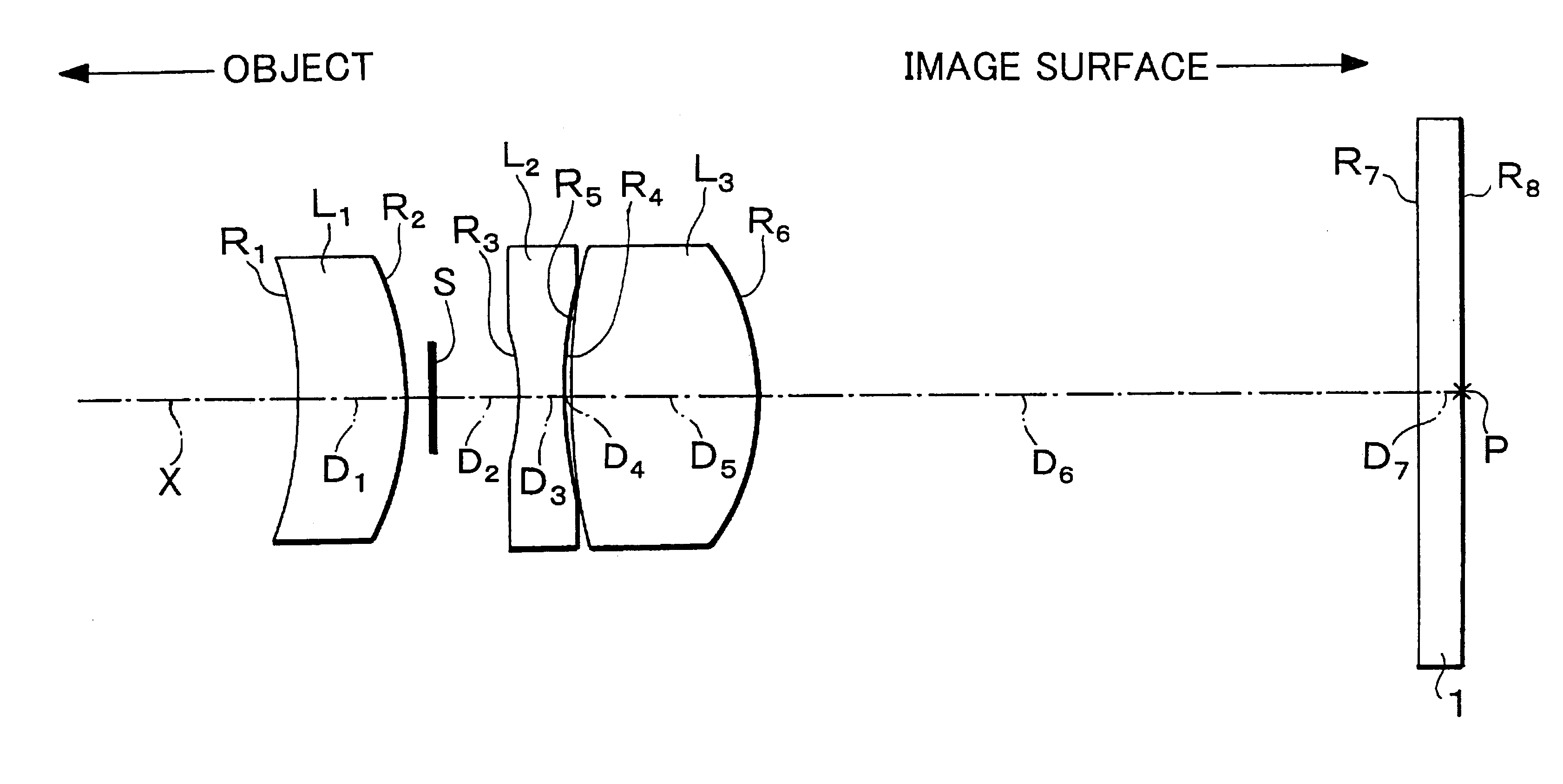
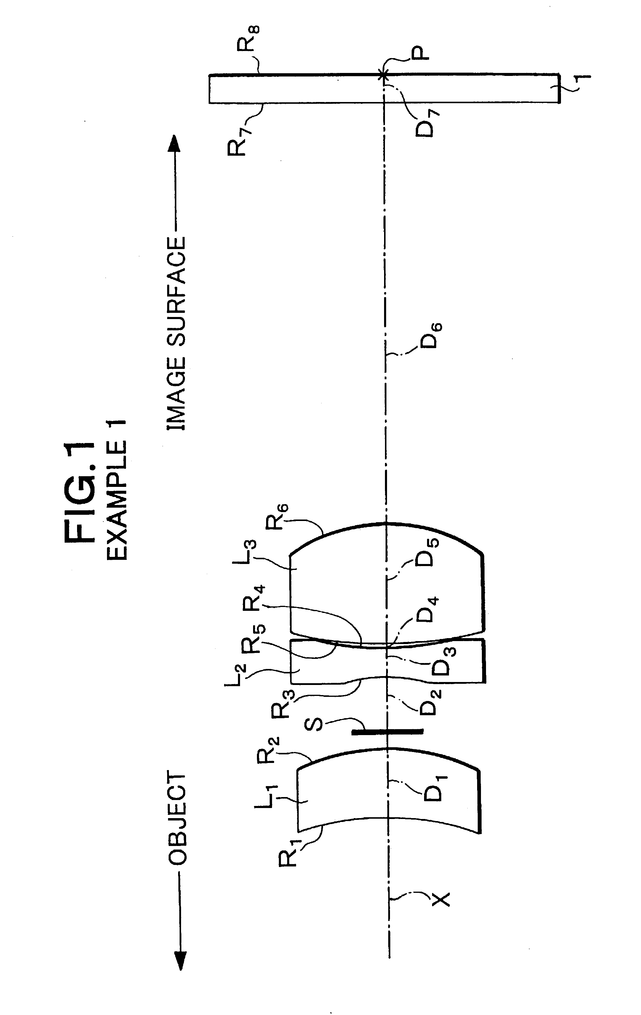
FIG. 1 shows the configuration of the single-focus lens in accordance with Example 1. This single-focus lens is configured as explained in the above-mentioned embodiment. Specifically, the single-focus lens comprises, successively from the object side, a first lens L.sub.1 made of a meniscus lens with a positive refracting power having aspheric surfaces on both sides with a convex surface directed onto the image surface side, a stop S, a second lens L.sub.2 made of a biconcave lens having a surface with a greater curvature directed onto the object side, and a third lens L.sub.3 made of a biconvex lens having an aspheric surface on the image surface side with a surface having a greater curvature directed onto the image surface side.

The upper part of the following Table 1 shows the focal length f', Fno., and angle of view 2.omega. of this single-focus lens. The middle part of Table 1 shows the radius of curvature R of each lens surface, the center thickness of each lens and the air sp...

example 2

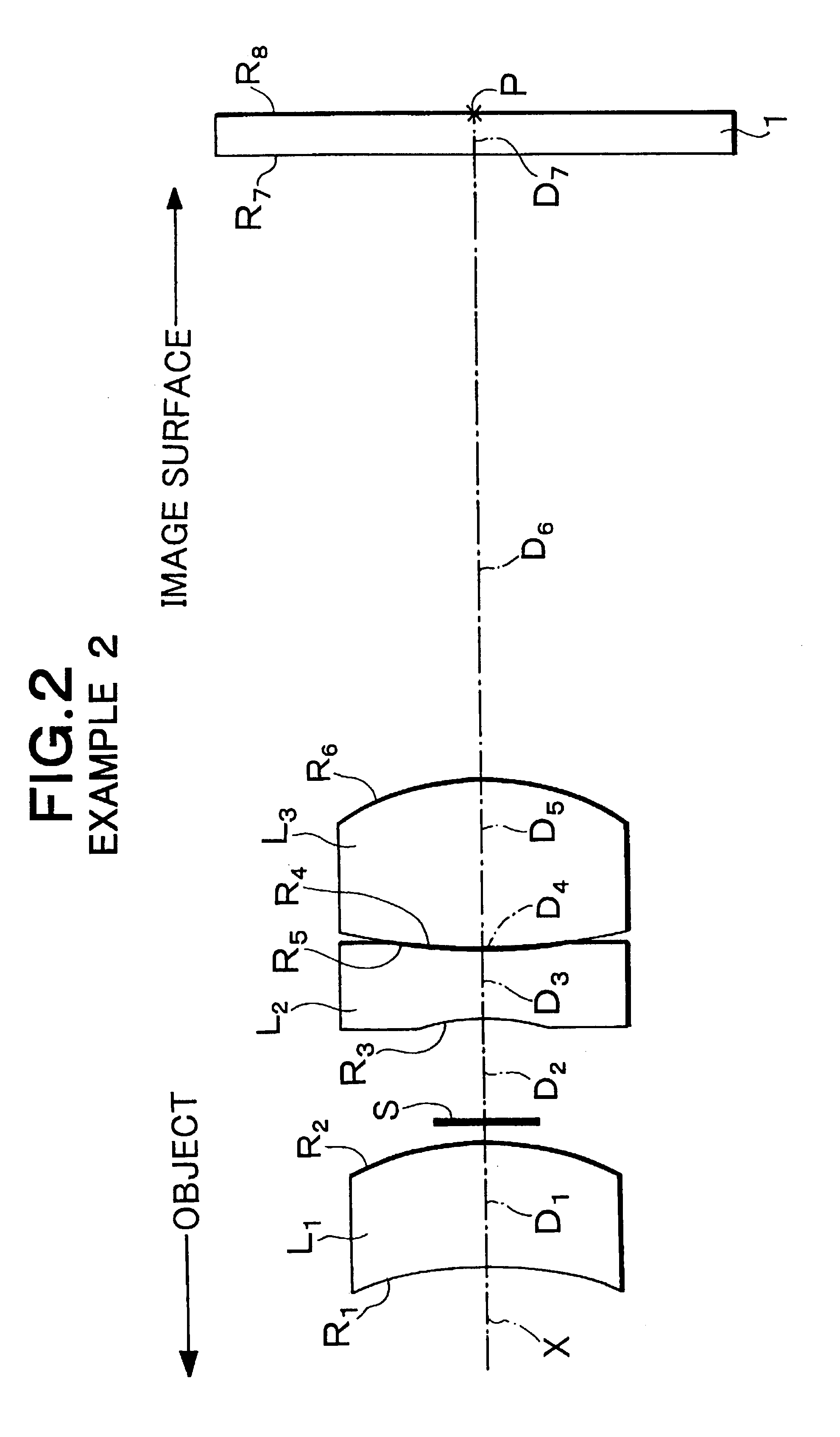
FIG. 2 shows the configuration of the single-focus lens in accordance with Example 2. This single-focus lens has a configuration substantially the same as that of Example 1. The upper part of the following Table 2 shows the focal length f', Fno., and angle of view 2.omega. of this single-focus lens. The middle part of Table 2 shows the radius of curvature R of each lens surface, the axial surface space D of each lens, and the refractive index N and Abbe number .nu. of each lens at d-line. The radius of curvature R and axial surface space D are standardized with respect to the focal length 1.00 (mm) of the whole lens system. Here, the surface number successively increases from the object side, whereas the surfaces indicated by "*" on the left side of their surface numbers refer to aspheric surfaces. The lower part of Table 2 shows the values of constants K, A.sub.4, A.sub.6, A.sub.8, and A.sub.10 of each aspheric surface shown in the above-mentioned aspheric surface expression. Also,...


PUM


Abstract

A single-focus lens includes from the object side, a first lens with a positive refracting power having at least one aspheric surface, a stop, a second lens with a negative refracting power, and a third lens with a positive refracting power having at least one aspheric surface. This single-focus lens further satisfies the conditional expression of 0.3<f / f2'3<0.8, where f is the focal length of the lens as a whole, and f23 is the composite focal length of the second and third lenses.

Description

This application claims the priority of Japanese Patent Application No. 2001-350913 filed on Nov. 16, 2001, which is incorporated herein by reference.1. Field of the InventionThe present invention relates to a single-focus lens suitable as a taking lens for an imaging device having a small size; and, in particular, to a single-focus lens with a simple configuration having a high optical performance.2. Description of the Prior ArtRecently, along with the advance in CCD manufacturing techniques, small-sized CCD cameras such as electronic still cameras have begun utilizing a high-density CCD whose number of pixels reaches the order of one million while each pixel reduces its size. Consequently, taking lenses for CCD cameras are desired to have a high resolution and high performances.Known as taking lenses responding to such a demand are those disclosed in Japanese Unexamined Patent Publication No. HEI 5-157962 and No. HEI 11-125767, for example. The former is a front shutter type takin...

Claims


Application Information

Patent Timeline
Patent Type & Authority Patents(United States)
IPC IPC(8): G02B13/18G02B9/12G02B9/16G02B13/00
CPCG02B9/16G02B13/0035
Inventor SATO, KENICHI
Owner TIANJIN OFILM OPTO ELECTRONICS CO LTD
Why Eureka
Try Eureka