Security system with maskable motion detection and camera with an adjustable field of view

Inactive Publication Date: 2004-04-27
PHILIPS ELECTRONICS NORTH AMERICA +1
View PDF16 Cites 142 Cited by
  • Summary
  • Abstract
  • Description
  • Claims
  • Application Information

AI Technical Summary

Problems solved by technology

Motion detection systems are not as effective in the security of areas within which activity is normally expected, because the number of alarms which will be sent will overburden the monitor.
Conventionally, systems which provide for pan, tilt and zoom cameras (hereinafter P/T/Z cameras) are incompatible with motion detection systems.
Experience has shown that monitors commonly forget to reenable the motion detector, obviating their effectiveness as a security device.
P/T/Z camera systems are further incomp

Method used


Image

  • Security system with maskable motion detection and camera with an adjustable field of view
  • Security system with maskable motion detection and camera with an adjustable field of view
  • Security system with maskable motion detection and camera with an adjustable field of view

Examples


Example

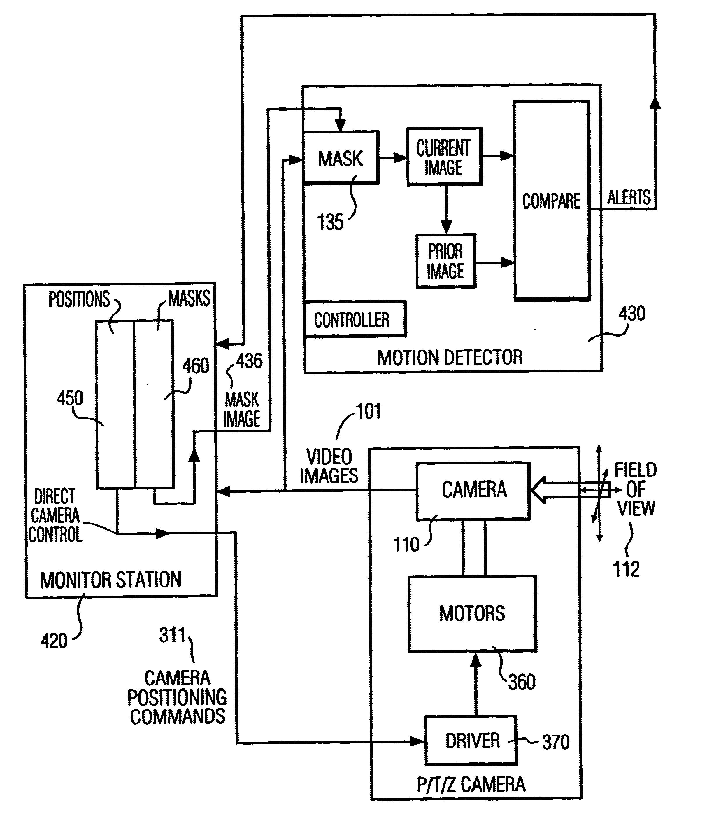
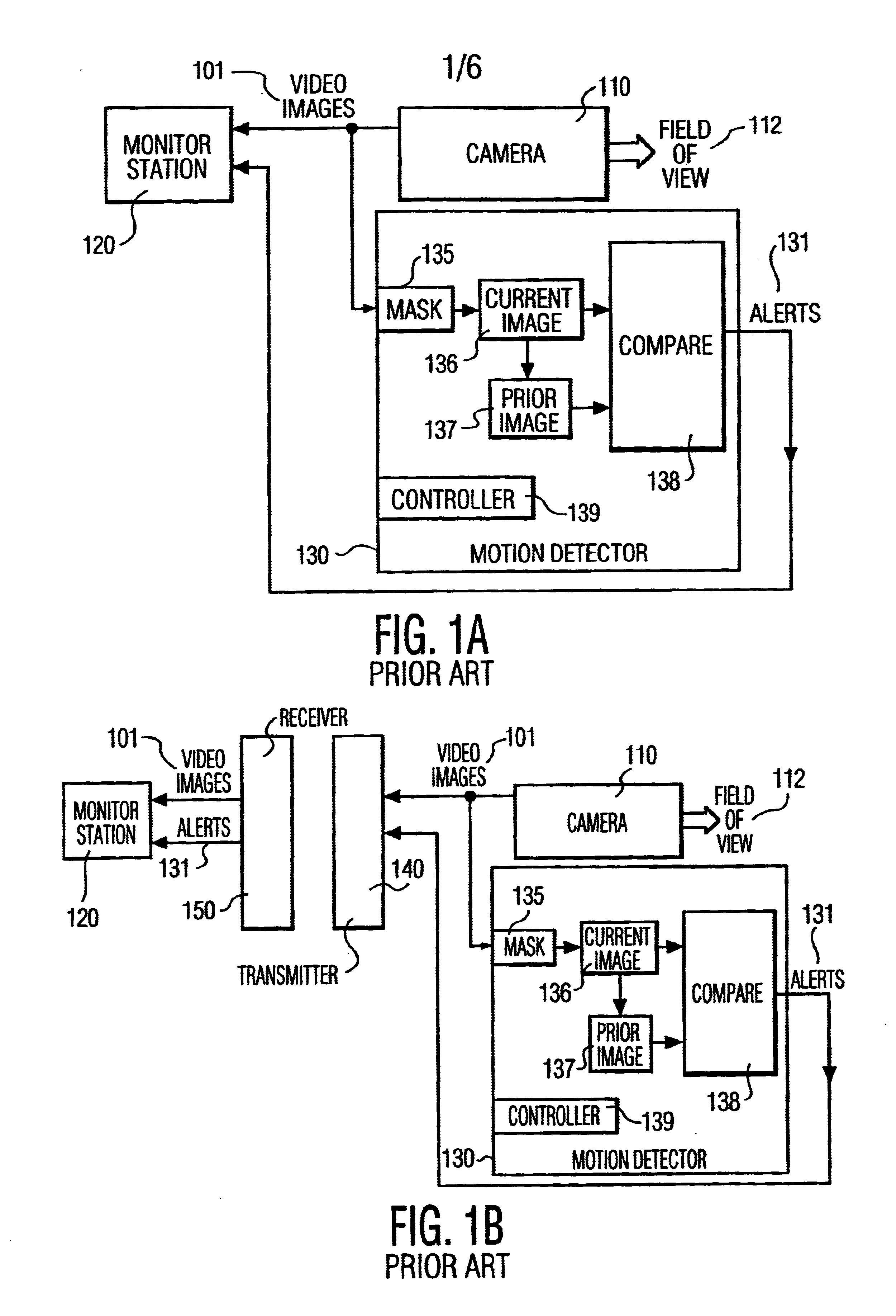
FIG. 1 shows a video security system with a motion detector, as known in the current art. Video images 101, in the form of frames, are produced by the camera 110. These images are representative of the camera's field of view 112. The field of view is established by the camera's location, orientation, and lens configuration. In FIG. 1a, the video images 101 are simultaneously sent to the monitor station 120 and the motion detector 130. The motion detector 130 compares a current image 136 to a prior image 137, under the control of a controller 139. The compare block 138 asserts an alert signal 131 whenever the current image 136 differs substantially from the prior image 137. The difference between the images may be measured by the number of picture elements (pixels) having a different value, for example. If the number of differing pixels exceeds a threshold value, an alert is transmitted to the monitor station. The use of a threshold allows the motion detector to be insensitive to sma...


PUM


Abstract

A security system with a Pan/Tilt/Zoom Camera and maskable motion detection is disclosed. At selected fields of view of the P/T/Z camera, masks are created to mask, from motion detection, select sub-areas within the selected field of view. The mask created for the selected view may be saved in memory. The saved mask may be recalled and reapplied to the motion detector whenever the P/T/Z camera is repositioned to the field of view corresponding to the saved mask. The commands required to reposition the camera to each selected field of view may also be saved. The mask and repositioning commands can be associated with each other, so that selecting a target view corresponds to selecting the commands to position the camera to that view, as well as the mask to be applied for this view.

Description

1. Field of the InventionThis invention relates to security systems, specifically security systems which employ video equipment for motion detection. Disclosed is a system which allows for motion detection of selected areas within the field of view of a video camera. This system contains an integrated control system which dynamically and automatically updates the motion detection mask to correspond to alternative views, based upon a predetermined set of criteria associated with such views.2. Discussion of the Related ArtVideo systems are well known in the field of security systems. In a typical security system, one or more video cameras are placed so as to provide a field of view of the area under surveillance. These video cameras convert a visual image into an electronic form suitable for transmission. A control station, either co-located within the surveillance area or remote from the area, receives the signals from these cameras and displays the video image at a console, for secu...

Claims


Application Information

Patent Timeline
IPC IPC(8): G08B13/194H04N7/18G08B13/196G08B25/00
CPCG08B13/19602G08B13/19606G08B13/19689H04N7/183G08B13/194
Inventor RANDALL, JENNIFER L.
Owner PHILIPS ELECTRONICS NORTH AMERICA
Why Eureka
Try Eureka