
Retrofitting vessels to deflect radar signals

a technology for retrofitting vessels and radar signals, applied in the direction of antennas, weapons, offensive equipment, etc., can solve the problems of increasing the cost of incorporating such designs, increasing the risk of detection and possible attack of air-borne and water-borne defence vessels, and increasing the risk of being damaged by the impact of the damage,

Inactive Publication Date: 2004-05-18
TENIX DEFENCE
View PDF10 Cites 26 Cited by
  • Summary
  • Abstract
  • Description
  • Claims
  • Application Information

AI Technical Summary

Benefits of technology

The orientation of the faces is preferably such that the faces are oblique to the direction of incident radar for a given range of incident directions. Preferably any edges defining the boundary of the reflective surfaces are also oriented so as to be oblique to the direction of incident radar. In this embodiment of the invention, with a surface orientation that is oblique to the direction of incident radar, the strength of the return signal is then only proportional to the square of the length of the edge of the surface normal to the incident radar. If the face is oblique to the direction of incident radar, and the edges of the surface are oblique to the direction of incident radar, then only the corners of the surface will reflect as point sources. As points have no spatial dimension, the strength of the return signal from each point will vary inversely with the square of the radar frequency. In this way the radar cross-section of the vessel, and hence its radar signature, can be reduced for a given range of incident radar directions.
The present invention is capable of providing a degree of control over the direction in which electromagnetic waves are redirected, permitting other directions as well as the incident direction to be avoided where required.
The arrangement of elements and / or the manner of installation of the array on a vessel structure is preferably such that the facets of the elements reflect the incident radar signal away from the threat direction. The arrangement is also preferably such that the facets of the array do not provide to any appreciable extent internal reflection sources whereby to reduce the likelihood of an incident radar signal being reflected towards an adjacent element in the array and in turn reflected back in the direction of the incident radar signal.
The array may be releasably attachable to the vessel. This may facilitate ease of maintenance of the vessel structure and / or replacement or modification of the characteristics of the array.

Problems solved by technology

Air-borne and water-borne defence vessels are under constant threat of detection and possible attack from non-friendly artillery such as ground-based, sea-going or air-borne weapons systems.
It will be appreciated that vessels incorporating such designs involve significant expense over and above the basic vessel.
With tightening of government spending generally and defence budgets specifically, the prospect of replacing an ageing fleet with a new fleet which incorporates an expensive design, even if the des may reduce the likelihood of loss of the vessel when on a war footing, is not an attractive proposition.
Radar absorbent materials of this type are expensive to purchase and install, and create major maintenance problems by trapping moisture and dirt and promoting corrosion of the substrate such as the ship super structure.

Method used


Image

  • Retrofitting vessels to deflect radar signals
  • Retrofitting vessels to deflect radar signals
  • Retrofitting vessels to deflect radar signals

Examples


Embodiment Construction

The present invention will now be described with reference to particularly preferred embodiments, in which:

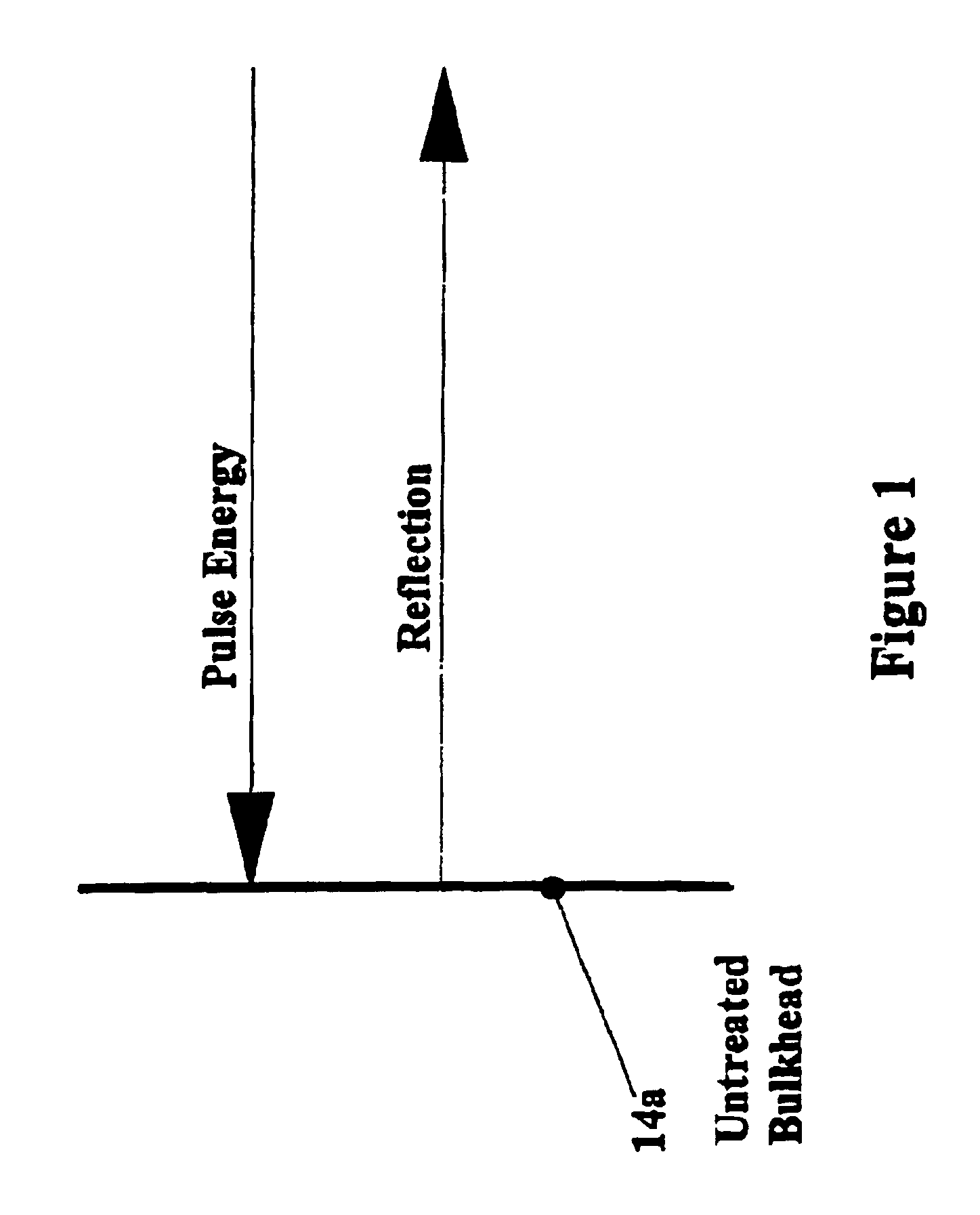
FIG. 1 is a schematic of the reflection pattern of a vessel without an array according to the invention;

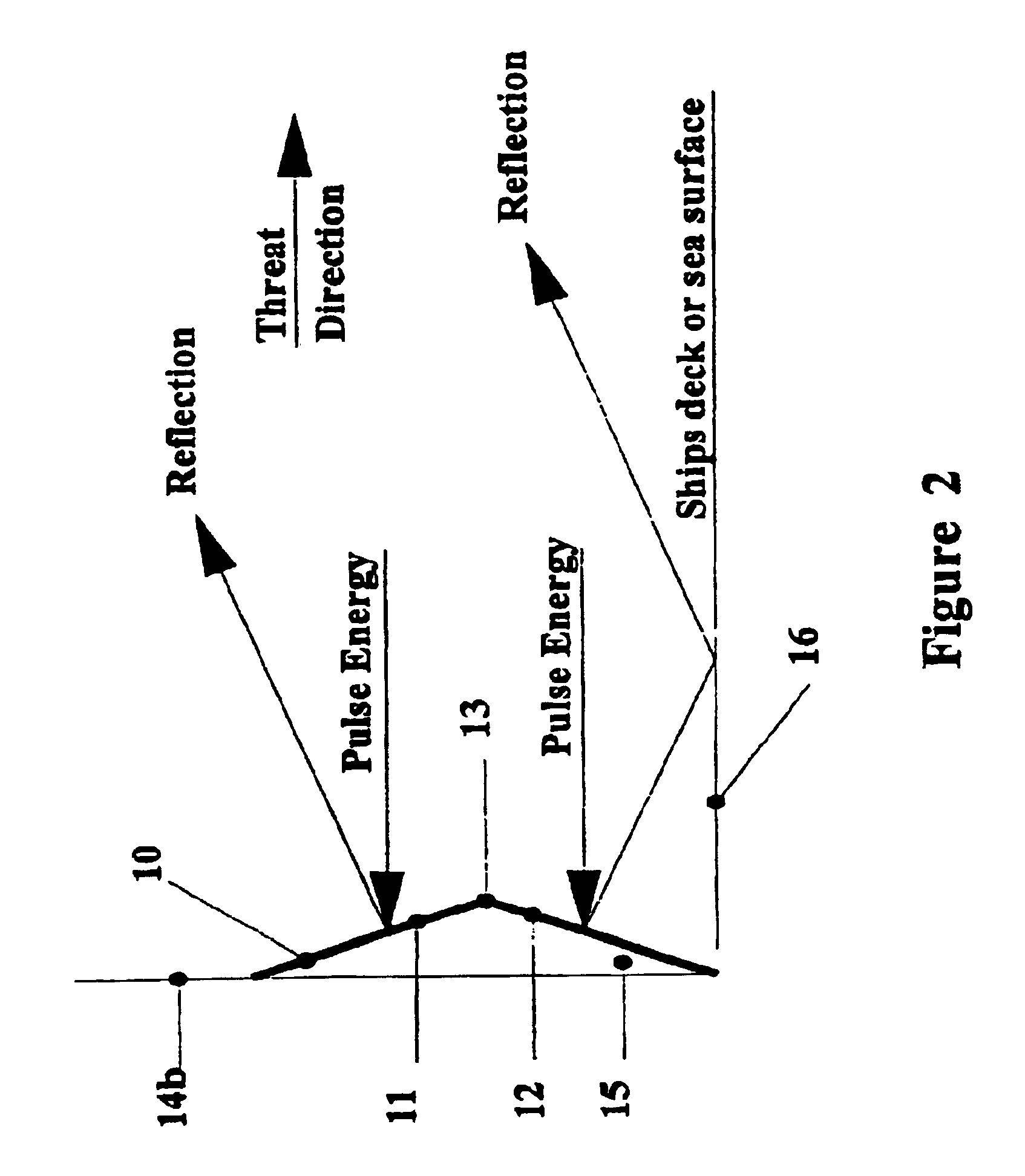
FIG. 2 is a schematic of the reflection profile of the bulkhead of a vessel structure to which one element of an array according to the invention is attached; and

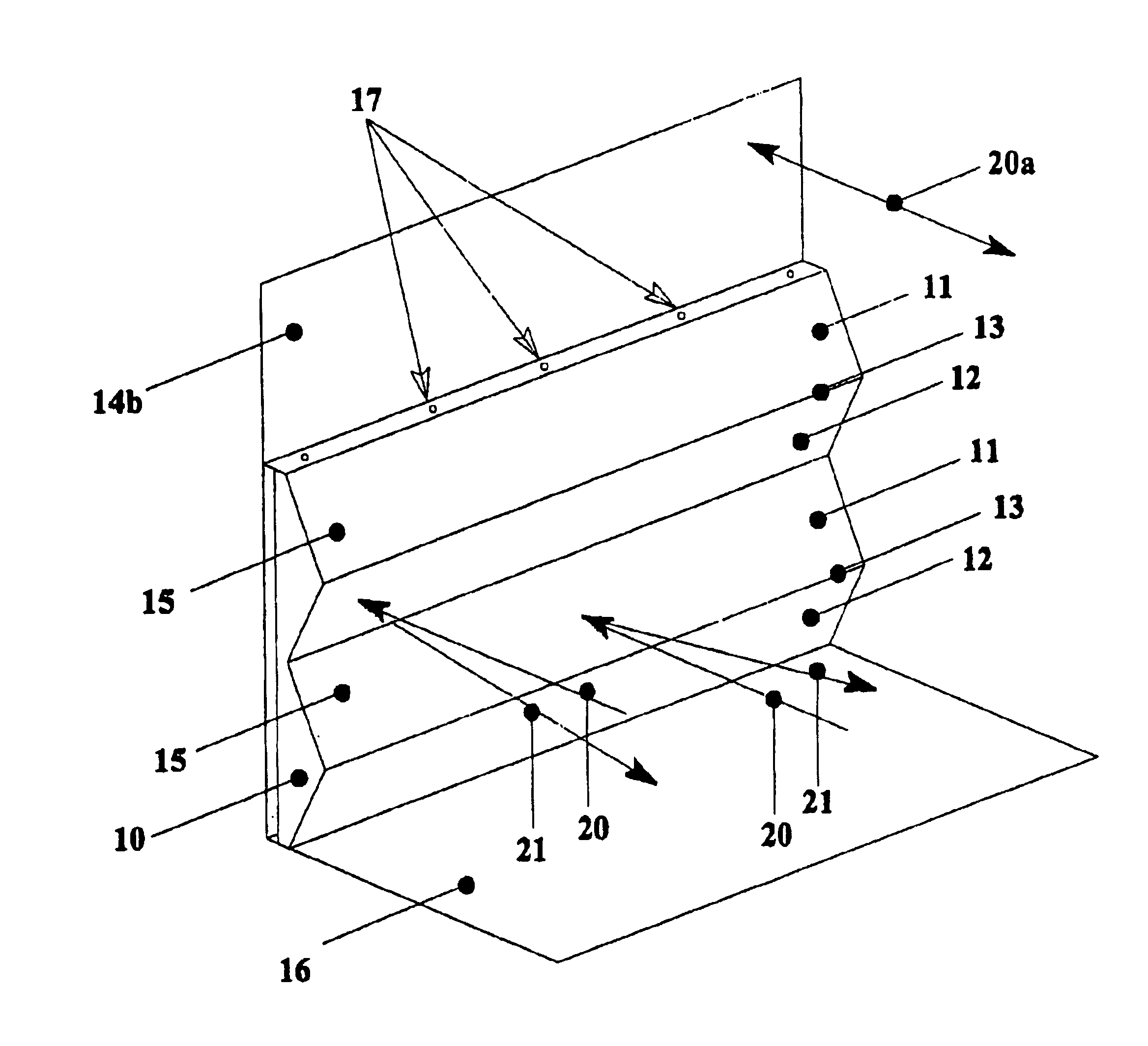
FIG. 3 is a cut-away perspective view of a side of a vessel to which an array according to the invention has been attached.

Turning to the drawings, FIG. 1 shows a vertical surface 14a comprising, symbolically, a bulkhead of a vessel structure. In this arrangement a substantially horizontal incident radar signal (designated in FIG. 1 as "pulse energy") string vertical surface 14a (being normal to the incident radar signal) is reflected from the vertical surface 14a directly back to the radar source (not shown). It will be appreciated that a consequence of this arrangement is that the surface by virtue of its cross-sec...


PUM


Abstract

The radar signature of a vessel is reduced by retrofitting it with an array (10) of elements (15) fastened to surfaces (14b) of the vessel. The elements (15) have planar faces (11-12) so oriented that incident radar signal (20) is reflected away from its angle of incidence.

Description

The present invention is directed to improvements in or relating to vehicles and structures, and is more particularly directed to methods for reducing the radar signature of structures by directing the radar reflections from structures away from specified directions.BACKGROUND TO THE INVENTIONAir-borne and water-borne defence vessels are under constant threat of detection and possible attack from non-friendly artillery such as ground-based, sea-going or air-borne weapons systems. Vessel detection is usually by means of radar, since conventional vessels, to a greater or lesser extent, all possess a radar signature.Radar operates by transmitting a pulse of electromagnetic energy and measuring the time between the transmitted pulse and the receipt of the reflection of the pulse from a target. The range at which a target can be detected is a function of, amongst other things, the intensity of the pulse energy and the size of the target (also known as radar cross-section) with respect to...

Claims


Application Information

Patent Timeline
Patent Type & Authority Patents(United States)
IPC IPC(8): B63G13/00B63G13/02F41H3/00
CPCB63G13/02F41H3/00H01Q15/18
Inventor STAFFORD, PHILIP K.
Owner TENIX DEFENCE
Learn More