Reflective LCD, semitransmitting reflective LCD and electronic device
a reflective display and semi-transmitting technology, applied in static indicating devices, instruments, non-linear optics, etc., can solve the problems of difficult simultaneous increase of brightness and contrast ratio, and great difficulty in precise color correction. achieve accurate grayscale display, increase brightness and contrast ratio, and high contrast ratio
- Summary
- Abstract
- Description
- Claims
- Application Information
AI Technical Summary
Benefits of technology
Problems solved by technology
Method used
Image
Examples
first embodiment
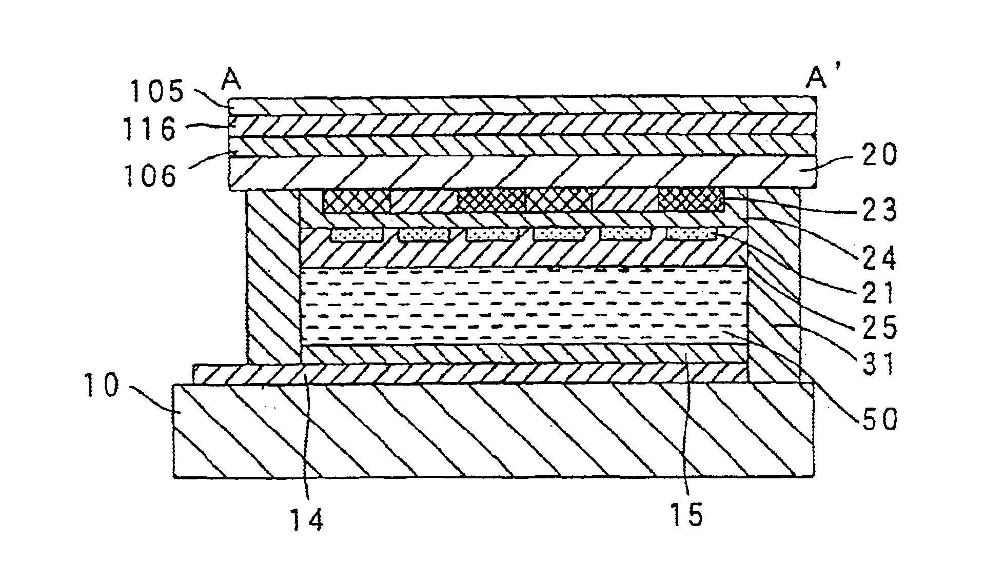
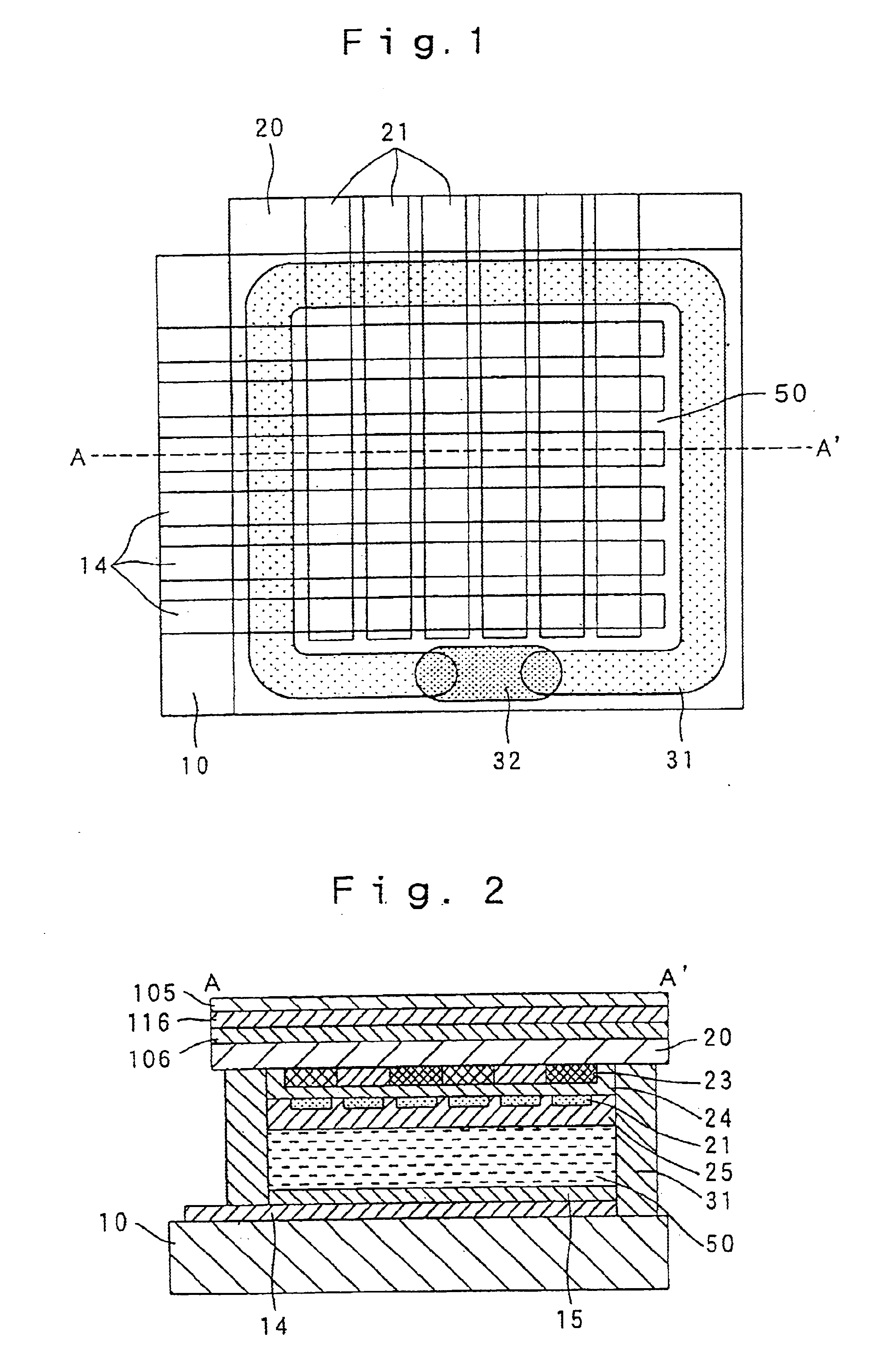
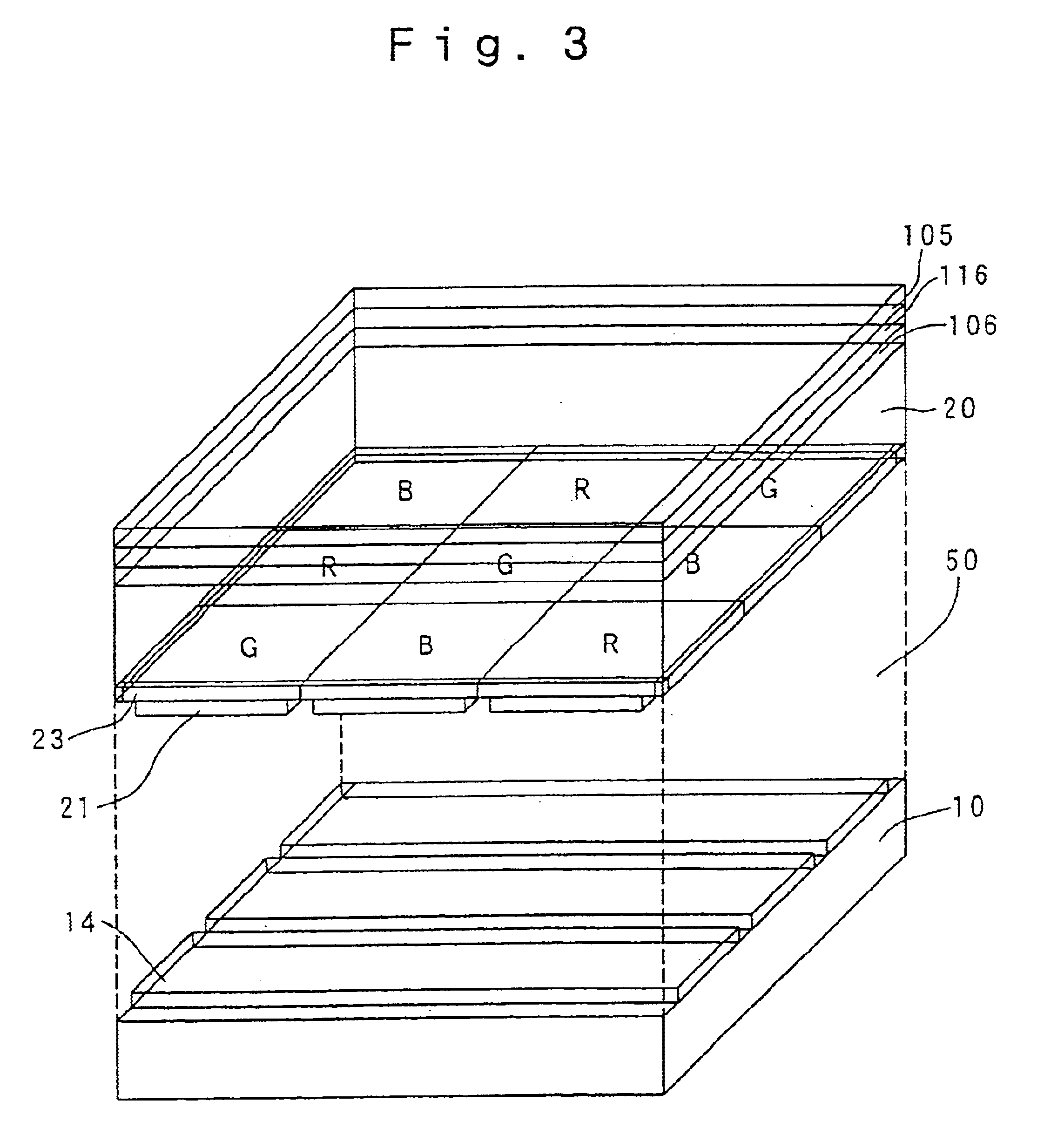
In various embodiments including this embodiment, each of the first retardation plate 106 and the second retardation plate 116 preferably comprises a biaxial retardation plate and satisfies the condition Nx>Nz>Ny (wherein Nx: refractive index in the X axis direction, Nz: refractive index in the Z axis direction, Ny: refractive index in the Y axis direction). This construction can widen the field of vision. However, even when each of the first retardation plate 106 and the second retardation plate 116 comprises a uniaxial retardation plate, the advantages of the first embodiment can be obtained.
second embodiment
A reflective liquid crystal device in accordance with a second embodiment of the present invention is described with reference to FIG. 7. The second embodiment of the present invention is different from the first embodiment in the parameter settings of the first retardation plate 106, the second retardation plate 116, and the polarizer 105, and the other components and operations are the same as the first embodiment shown in FIGS. 1 to 3.
Namely, like in the first embodiment, in the second embodiment, the twist angle .theta.t of the liquid crystal layer 50 comprising a STN liquid crystal is limited to 230 to 260 degrees, the minimum and maximum .DELTA.nd of the liquid crystal layer 50 are 0.85 .mu.m or less and 0.70 .mu.m or more, respectively.
Unlike in the first embodiment, in the second embodiment, .DELTA.nd of the first retardation plate 106 is 150.+-.50 nm, .DELTA.nd of the second retardation plate 116 is 610.+-.60 nm, the angle .theta.1 formed by the transmission axis or absorpt...
third embodiment
The third embodiment is different from the first or second embodiment in that unevenness is formed on the surface of the first substrate 10 to accordingly form unevenness on the reflecting electrodes 14 and the alignment film 15, and the thickness d of the liquid crystal layer 50 in each pixel slightly changes with position. The other components of the third embodiment are the same as the first or second embodiment.
Therefore, the third embodiment comprises a first substrate 10' having an uneven surface so that each of the reflecting electrodes 14 has an uneven surface facing the liquid crystal layer 50 and thus has a scattering surface (white surface) without a feel of mirror surface. Also, the angle of view can be widened by scattering due to the unevenness. The unevenness can relatively easily be formed by roughening the substrate with hydrofluoric acid. Like in the first or second embodiment, in the third embodiment, the minimum (value at a convex) and maximum (value at a concave...
PUM
 Abstract
Description
Claims
Application Information
 - R&D
- Intellectual Property
- Life Sciences
- Materials
- Tech Scout
- Unparalleled Data Quality
- Higher Quality Content
- 60% Fewer Hallucinations
Browse by: Latest US Patents, China's latest patents, Technical Efficacy Thesaurus, Application Domain, Technology Topic, Popular Technical Reports.
© 2025 PatSnap. All rights reserved.Legal|Privacy policy|Modern Slavery Act Transparency Statement|Sitemap|About US| Contact US: help@patsnap.com


