Sutureless anastomosis systems

an anastomosis system, sutureless technology, applied in the field of sutureless anastomosis system, can solve the problems of host vessel, significant time and complexity for stabilizers and retractors, tissue infarction,

Inactive Publication Date: 2004-05-25
CONVERGE MEDICAL
View PDF158 Cites 148 Cited by
  • Summary
  • Abstract
  • Description
  • Claims
  • Application Information

AI Technical Summary

Benefits of technology

One aspect of the invention provides fittings designed to exert radial force at the vessel attachment points to maintain bypass graft patency. The fittings may be used to secure biological bypass grafts obtained by harvesting vessels from the patient or synthetic bypass graft materials. When using harvested vessels, fitting embodiments permit everting the harvested vessel to maintain intima to intima apposition between the bypass graft and the host vessel. When using synthetic bypass graft materials, the fittings may be incorporated in the bypass graft design to eliminate the step of attaching the bypass graft to the fitting prior to deploying the bypass graft. The fittings, with bypass grafts attached, are advanced through the delivery system and are secured to the host vessel wall at target locations.

Problems solved by technology

Stenosed blood vessels cause ischemia potentially leading to tissue infarction.
Stabilizers and retractors still require significant time and complexity to expose the host vessel and suture the bypass graft to the host vessel wall.
Shunts not only add to the complexity and length of the procedure, but they require a secondary procedure to close the insertion sites proximal and distal to the anastomosis site.
These end-end devices are amenable to reattaching severed vessels but are not suitable to producing end-end anastomoses between a bypass graft and an intact vessel, especially when exposure to the vessel is limited.
Even though these and other clipping and stapling end-side anastomotic devices have been designed to decrease the time required to create the anastomosis, interruption of blood flow through the host vessel increases the morbidity and mortality of bypass grafting procedures, especially during beating heart CABG procedures.

Method used


Image

  • Sutureless anastomosis systems
  • Sutureless anastomosis systems
  • Sutureless anastomosis systems

Examples


Embodiment Construction

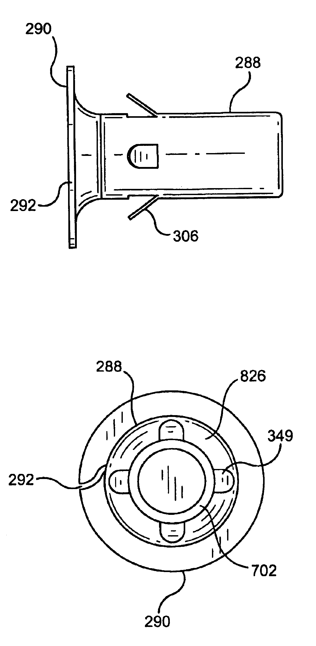
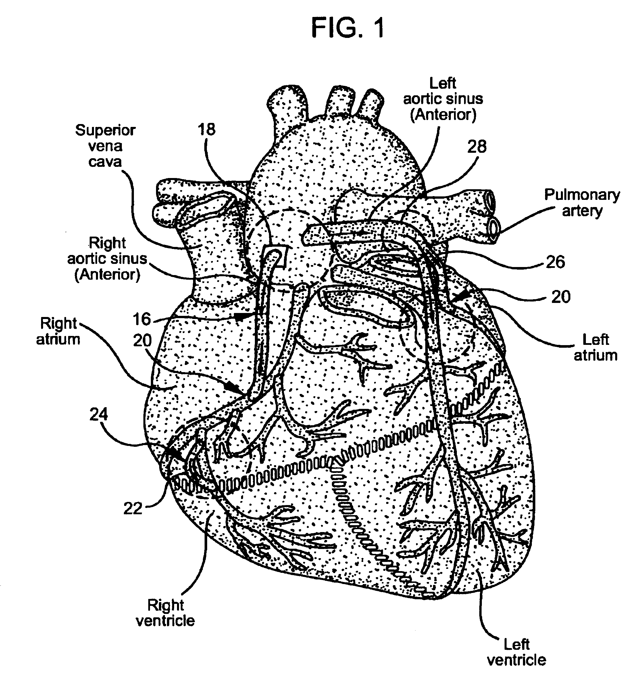
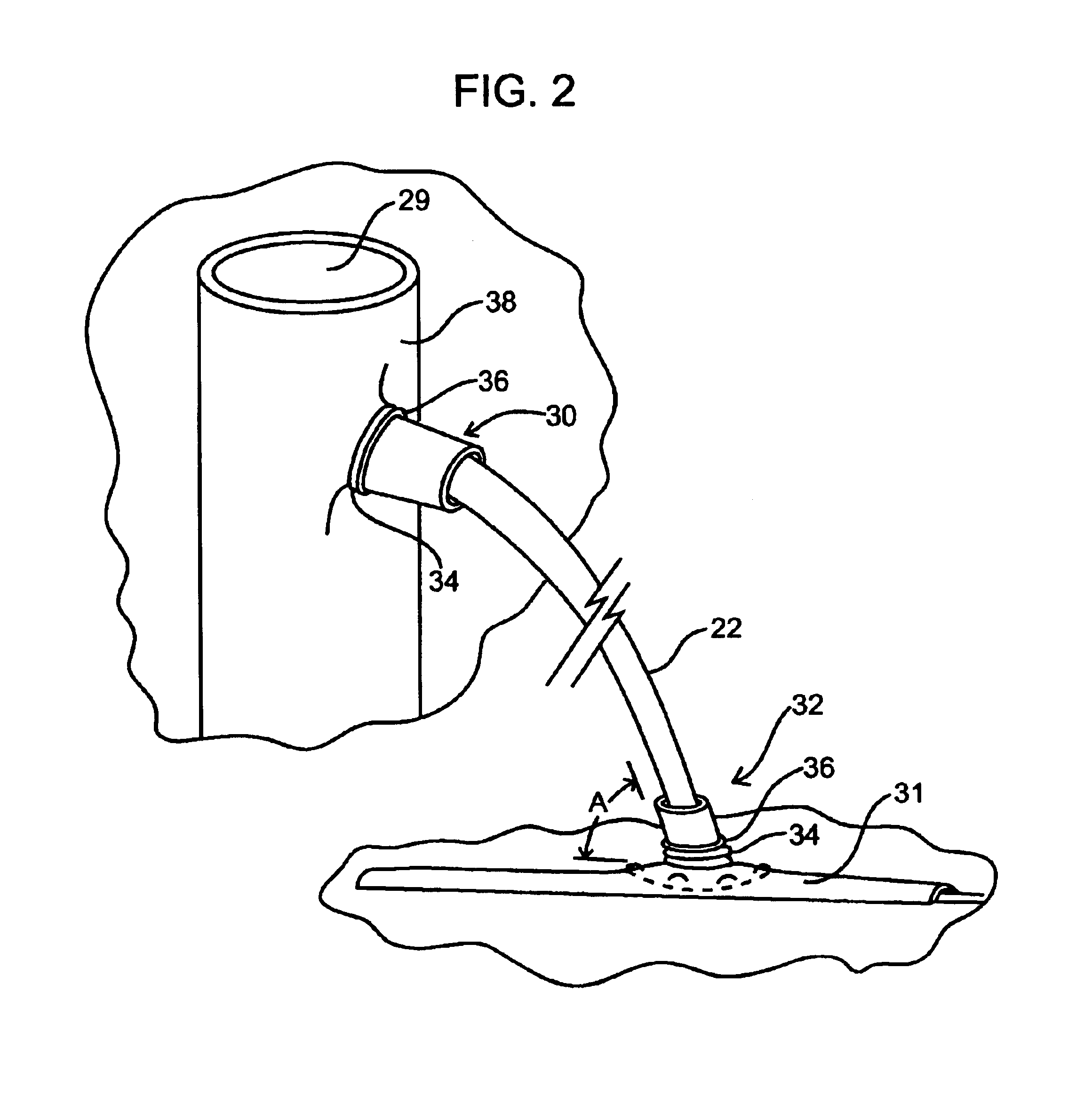
The fittings and delivery systems of the invention are intended to produce anastomoses between bypass grafts and host vessels to treat vascular abnormalities such as stenoses, thromboses, other occlusions, aneurysms, fistulas, or other indications requiring a bypass graft. The systems of the invention are useful in bypassing stented vessels that have restenosed. Current approaches for treating stenosed stents have not been successful at safely and reliably removing the lesion and opening the vessel lumen. Therefore the approach described by this invention, which produces a blood flow conduit around the stented lesion, mitigates concerns associated with damaging the stent or forming emboli while removing deposits attached to the stent. The fittings are also intended to secure and support the ends of transected vessels such as those cut during organ transplantations. The embodiments of the invention also provide mechanisms to secure branching vessels to a replacement graft during surg...


PUM


Abstract

Anastomosis systems include fittings and compression mechanisms for effecting end-end or end-side couplings of biological or synthetic bypass grafts to vessel locations. The fittings are tubular and surround end regions of the graft. In some applications an end region of the graft is everted and surrounds an exterior of the fitting, in which case the preferred compression mechanism is a retaining ring. A tool is used to evert the graft end region. In other applications, the fitting has an interior groove that receives an expandable retaining ring that urges the graft end region radially outwardly against the fitting. A graft deploying and securing system includes a needle for puncturing vessel tissue, a dilator, and a sheath adapted for containing a graft / fitting combination and guiding the combination into the vessel through an opening formed by the needle and dilator.

Description

This invention relates to devices for deploying and securing the ends of bypass grafts designed to provide a fluid flow passage between at least two host vessel regions (or other tubular structure regions). More particularly, the invention relates to bypass grafts that are secured at target host vessel locations thereby producing a fluid flow passage from the first host vessel location through the bypass graft and to the second host vessel location. The bypass grafts and deployment systems of the invention do not require stopping or re-routing blood flow to perform an anastomosis between a bypass graft and a host vessel. Accordingly, this invention describes sutureless anastomosis systems that do not require cardiopulmonary bypass support when treating coronary artery disease.Current techniques for producing anastomoses during coronary artery bypass grafting procedures involve placing the patient on cardiopulmonary bypass support, arresting the heart, and interrupting blood flow to ...

Claims


Application Information

Patent Timeline
Patent Type & Authority Patents(United States)
IPC IPC(8): A61B17/11A61F2/06A61B17/03A61B17/00A61B17/30A61B17/32
CPCA61B17/11A61F2/064A61B17/32053A61B2017/00867A61B2017/1107A61B2017/1135A61B2017/306A61F2/91
Inventor HOUSER, RUSSELL A.WHAYNE, JAMES G.FLEISCHMAN, SIDNEY D.
Owner CONVERGE MEDICAL
Why Eureka
Try Eureka