Pneumatic valve return spring

a technology of pneumatic valves and return springs, which is applied in the direction of valve arrangements, non-mechanical valves, machines/engines, etc., can solve the problems of loss of performance, complicated and unreliable variation of valve timing to achieve better fuel economy or engine performance, and the loss of conventional springs and valve assemblies

Inactive Publication Date: 2004-06-08
BOSSCHER RICHARD J
View PDF12 Cites 41 Cited by
  • Summary
  • Abstract
  • Description
  • Claims
  • Application Information

AI Technical Summary

Benefits of technology

Another objective of this invention is to provide such a pneumatic valve spring device which is simple in construction and installation and requires little or no modification to be inserted in place of conventional valve springs.
A further objective of this invention is to provide a pneumatic valve spring which lends itself to the elimination of valve float as well as being able to accommodate timing changes in the valve train cycle to increase engine power and / or economy.
An additional object of this invention is the provision of a pneumatic valve spring which is constructed to work in the high heat and oily environment of an internal combustion engine with great reliability.

Problems solved by technology

Conventional spring and valve assemblies suffer from a number of problems.
One such problem is that of metal fatigue of the springs themselves which can cause them to break and the valve to fail with major mechanical failure consequences in engines turning at high revolutions.
In purely mechanical valve spring arrangements, varying the timing of the valves to achieve better fuel economy or engine performance is extremely complicated and unreliable and thus generally not worth the effort due to the potential consequences from an increased risk of failure of the valve system.
Such purely mechanical valve spring systems also suffer from other maladies during high revolutions of the engine in that they tend to float or fail to close the valve quickly enough resulting in loss of performance and sometimes engine failure should the float be too extreme.
Such pneumatic assemblies however, often require exotic dedicated cylinder head assembly machining utilizing drilled air supply distribution passages, integral valve return spring operating bores, complex valve stem seals, oiling arrangements, sealing bellows and sophisticated air control arrangements.
Such exotic purpose-built or dedicated cylinder head valve operating systems remain largely unavailable due to the extreme costs involved with engineering, testing and manufacturing.
All of these attempts add to the complexity and cost of a high performance competitive engine and tend to reduce the inherent reliability of the same.
As a consequence, such pneumatic valve biasing assemblies are virtually impossible to use to retrofit the millions of existing internal combustion engines and are not cost effective when used as original equipment due to the major amount of machining and retooling required to implement the current complicated systems.
However, Speckhart is not easily retrofited to the millions of existing engines due to its interface with the valve.
Also, Speckhart communicates the pressurized air in the pneumatic spring directly to the valve stem itself thereby causing sealing problems.
However, the dual donut or flexible baffle arrangement taught by Vallve would be unreliable in the high heat and friction environment encountered by valve springs in internal combustion engines.
Burger is thus not an easy or desirable retrofit to existing vehicles and requires a complicated electromagnet system which would increase cost and would be prone to failure in the high heat and oily environment of engine valves.
However, Ericson by design is not easily installed to retrofit existing valve springs on engines and even as original equipment would require a complete redesign of valve actuation in conventional internal combustion engines.

Method used


Image

  • Pneumatic valve return spring
  • Pneumatic valve return spring
  • Pneumatic valve return spring

Examples


Embodiment Construction

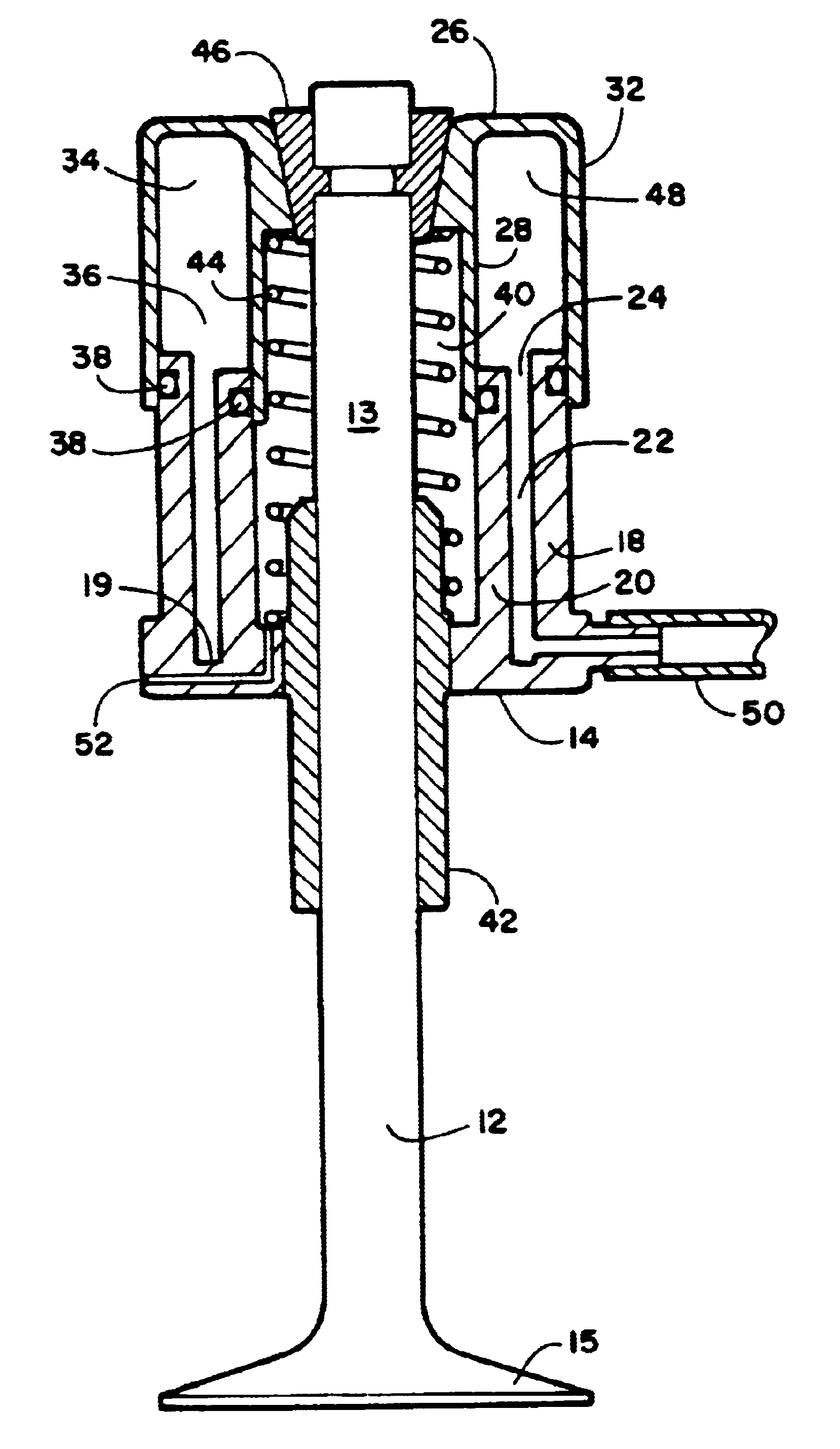
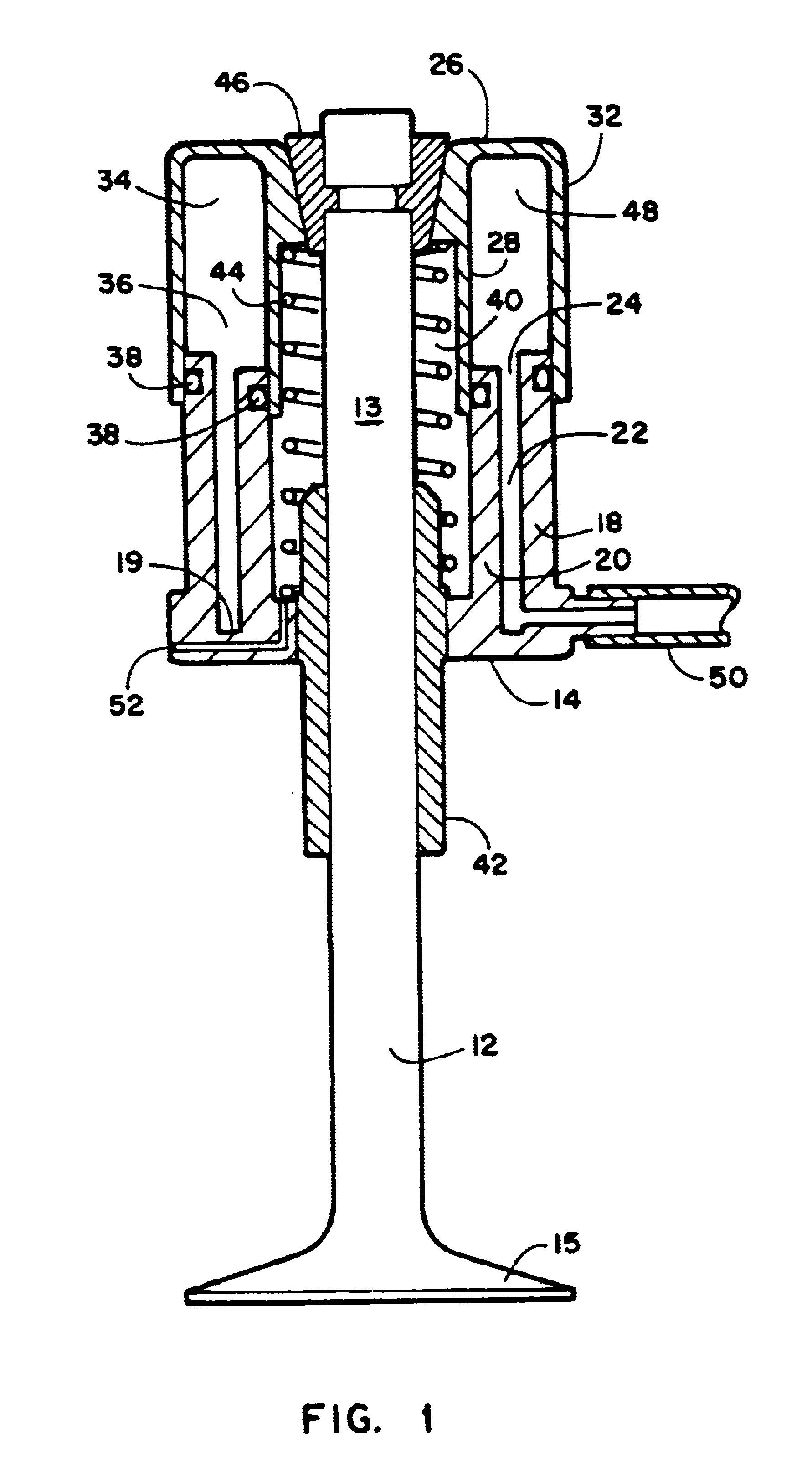
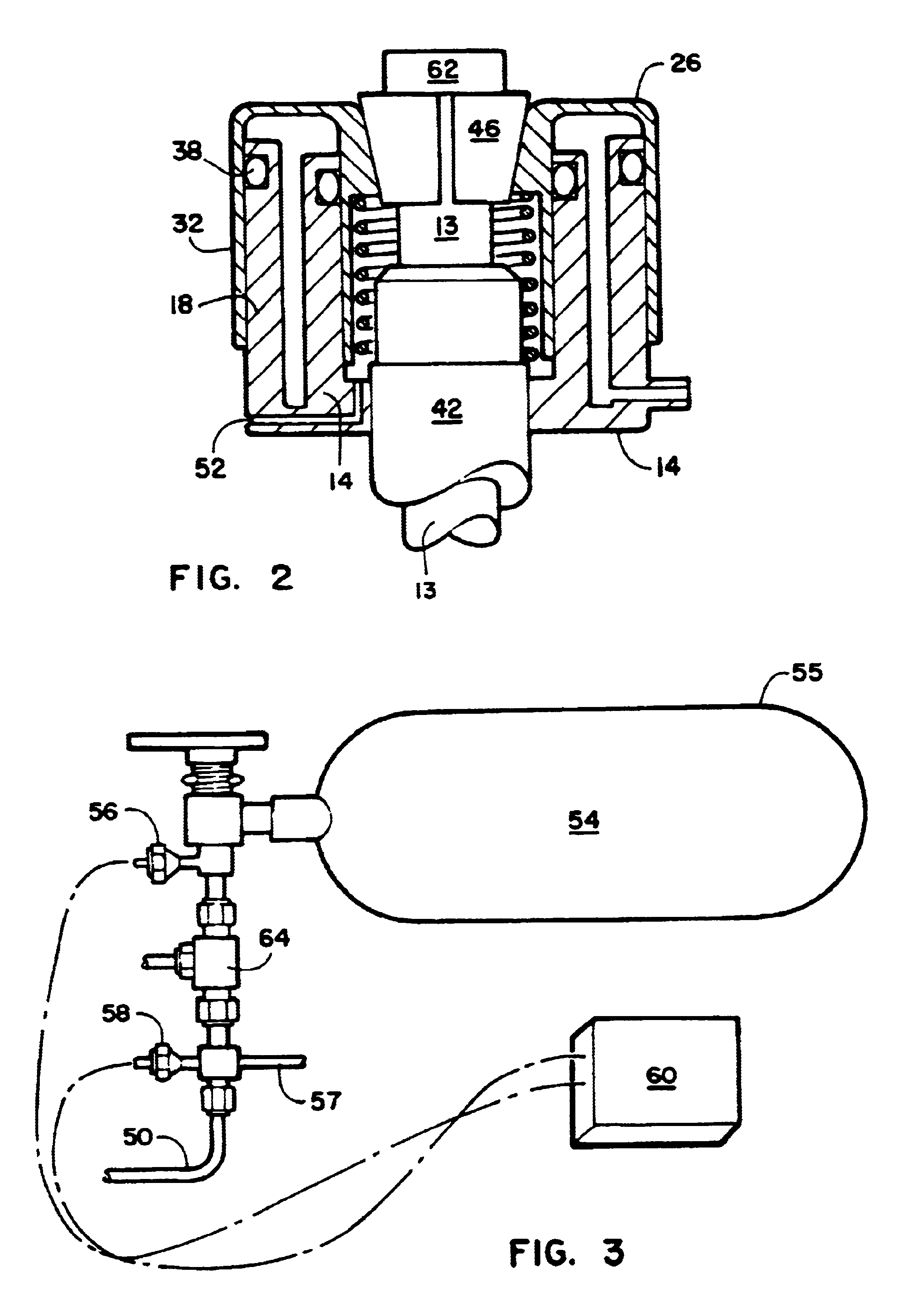
Referring now to the drawings, FIGS. 1-4 disclose the pneumatic valve biasing device 10 which is used in combination with valves 12 which reciprocate between open and closed positions in conventional engines and motors which use valves 12 for both intake of fuel mixtures and exhaust of spent gases.

A static housing 14 in the current best embodiment is essentially donut shaped and is mounted to a fixed position engaged with the cylinder head or engine employing the valve 12. A static aperture 16 defined by an outer wall 18 connected by a bottom wall 19 to an inner wall 20 of the static housing 14 surrounds a conventional valve 12 used in combination herewith. The outer wall 18 of the static housing 16 is circumferentially parallel and substantially equidistant from the inner wall 20 and thereby defines a static chamber 22. An opening opposite the bottom wall 19 forms a static circular aperture 24 communicating with the static chamber 22.

The dynamic housing 26, shaped similar to the st...


PUM


Abstract

A valve spring device using pressurized gas for use in biasing a reciprocating valve which moves between a seated position and open position. The device features a static housing having a static chamber what is translateably engaged with dynamic housing. Chambers inside both housings are sealably engaged such that the dynamic housing translates away from the static housing when pressurized gas is communicated to the engaged sealed chambers thereby biasing the dynamic housing away from the static housing and moving the attached valve. Timing of oscillation of the translation and resulting valve timing is controlled by a controller activating a control valve between a pressurizing state and a venting state. The timing may be adjusted to accommodate the engine timing through varying the controller's activation of the control valve and optionally varying the pressure of the gas using a regulator.

Description

1. Field of the InventionThe present invention relates to valve return springs. More particularly it relates to a device which replaces conventional metal valve return springs with pneumatic spring returns. The device is suited for use on a wide variety of applications where metal return springs are conventionally employed to bias valves toward a first position opposing a mechanical or other force which moves the valves toward and to, a second position. The device is especially well suited for retrofiting conventional mechanical valve return spring assemblies used on internal combustion and other cycled engines. However, it would also serve well as an original equipment pneumatic valve return spring to replace conventional spring assemblies and provide a wide degree of utility and performance improvement in both the function and timing of such valve assemblies used on internal combustion and other engines employing valves for venting and / or intake.2. Prior ArtValve springs are widel...

Claims


Application Information

Patent Timeline
Patent Type & Authority Patents(United States)
IPC IPC(8): F01L1/00F01L1/46F01L9/02F01L3/10F01L9/00F01L9/16
CPCF01L1/462F01L1/465F01L3/10F01L9/026F01L1/34F01L9/16
Inventor BOSSCHER, RICHARD J.
Owner BOSSCHER RICHARD J
Why Eureka
Try Eureka