
System and method for solid modeling

a solid modeling and system technology, applied in the field of three-dimensional (3d) solid modeling, can solve the problems of limited limited support for team or collaborative activities, and limited features of existing solid modeling programs, so as to support engineering team collaboration in the design and manufacturing process and effectively manage changes, the effect of saving significant production and experimentation costs

Inactive Publication Date: 2004-06-08
ALIBRE
View PDF20 Cites 14 Cited by
  • Summary
  • Abstract
  • Description
  • Claims
  • Application Information

AI Technical Summary

Benefits of technology

"The present invention is a system and method for three-dimensional modeling for mechanical engineers and designers. It is a distributed processing system that allows for the efficient and effective use of high-bandwidth networks, such as the Internet, to access and process data. The invention provides a more pervasive computing environment, allowing for increased processing efficiencies and options for corporate infrastructure investment. It also provides a more robust and flexible team or collaborative activities model, allowing for the outsourcing of any or all of the components of the platform. Overall, the invention provides greater access to applications and data, increased processing power, and more effective use of the Internet as a computing platform."

Problems solved by technology

Physical testing and many other performance models can also be modeled and visualized prior to the actual creation of the part, thereby saving significant production and experimentation costs.
Due in part to the constraints of these prior computing platforms, existing solid modeling programs have few features and limited support for team or collaborative activities.
Thus, supporting engineering team collaboration in the design and manufacturing process and effectively managing changes has been virtually impossible.
Further, current computer aided design (CAD) systems require a large internal corporate infrastructure to support the hardware, software and networks required for such a system to function properly.
Further, the effective use of the Internet / intranet as a computing platform diminishes the necessity for companies to maintain large complex corporate infrastructures by clearing the way for outsourcing of those activities to service providers.

Method used


Image

  • System and method for solid modeling
  • System and method for solid modeling
  • System and method for solid modeling

Examples


Embodiment Construction

The present invention will now be described more fully hereinafter with reference to the accompanying drawings, in which preferred embodiments of the invention are shown. This invention may, however, be embodied in many different forms and should not be construed as limited to the embodiments set forth herein; rather, these embodiments are provided so that this disclosure will be thorough and complete, and will fully convey the scope of the invention to those skilled in the art.

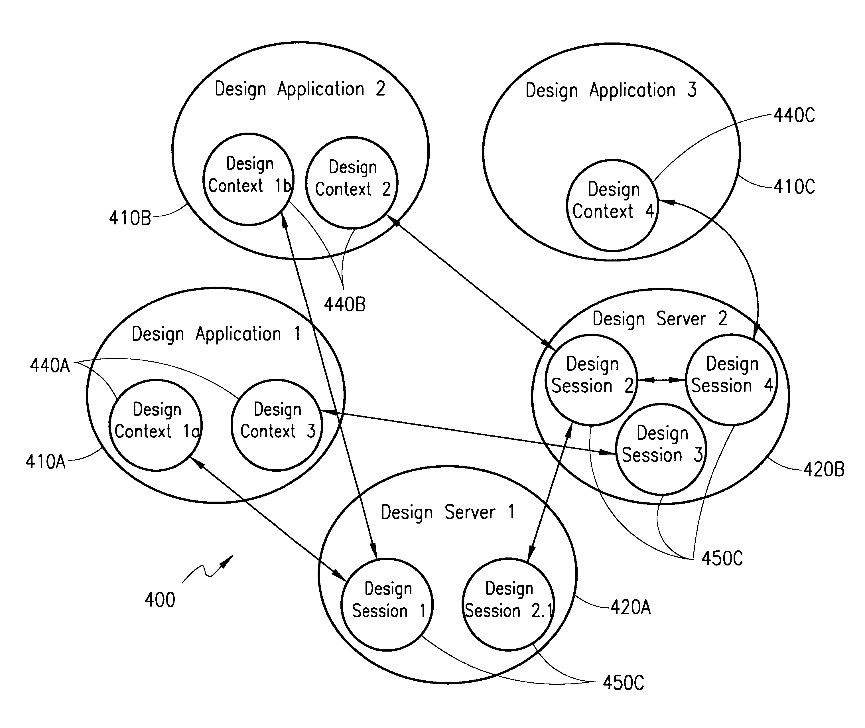
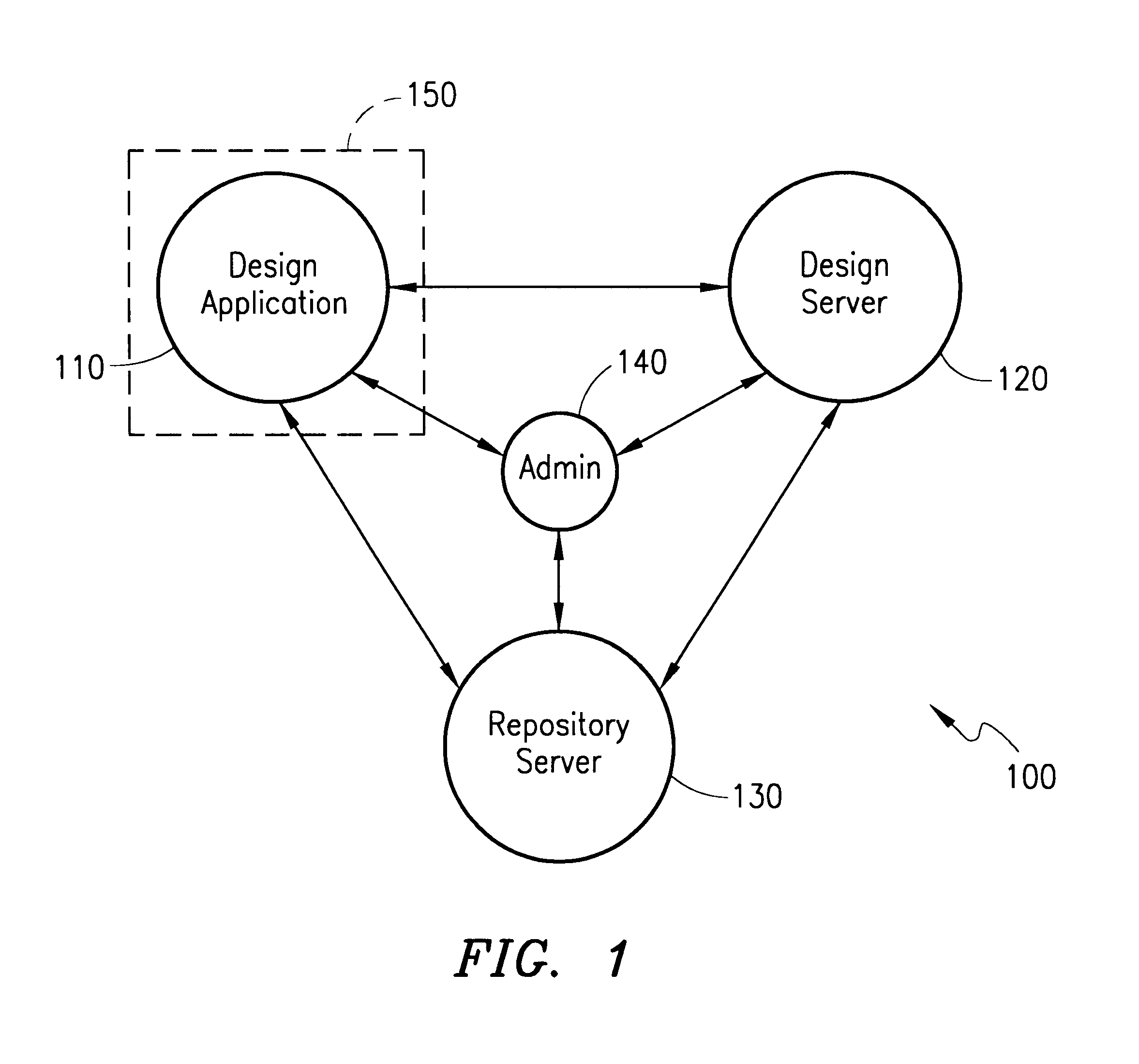
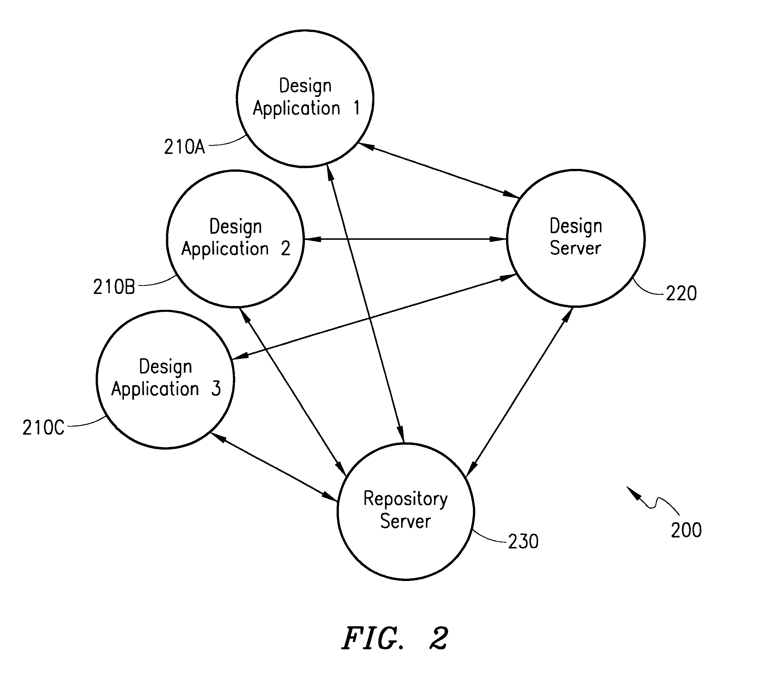
With reference now to FIG. 1 of the Drawings, a first embodiment of the present invention includes a multi-tier, distributed processing architecture, generally designated therein by the reference numeral 100. As illustrated in FIG. 1, a design application 110 is in communication with a design server 120, a repository server 130 and an administrative node 140, where each of the representative nodes 110, 120, 130 and 140 are in communication with each other.

It should be understood that design application 110 is...


PUM


Abstract

Modeling three-dimensional objects on a computer system via a high bandwidth distributed network, facilitating the computing of intensive computer-aided design (CAD) tasks to take place on a series of servers. A multi-tiered distributed processing architecture, which separates client user interface, multiple application servers and database servers is employed, resulting in the separation of server computing and data storage from the client control device. Computing for CAD tasks is directed to the client device or to an application server, as is appropriate for the complexity of tasks being performed.

Description

BACKGROUND OF THE PRESENT INVENTION1. Field of the InventionThe present invention relates to the field of three-dimensional (3-D) solid modeling for mechanical engineers / designers. More specifically, the present invention is directed to a system and method accessing computer applications and servers to manage distributed processing related to 3-D solid modeling for mechanical engineers / designers.2. Description of the Related ArtThe visualization of three-dimensional objects on a computer screen has enabled designers to model real world physical objects without the need to actually create the object. Using the enhanced computer graphics capabilities of current computers, designers can model an increasing variety of objects in various circumstances. For example, mechanical engineers in the automotive and aeronautical engineering disciplines can model discrete parts, collections of parts or whole assemblies on the computer. Physical testing and many other performance models can also be...

Claims


Application Information

Patent Timeline
Patent Type & Authority Patents(United States)
IPC IPC(8): H04L29/06H04L29/08G06F17/50
CPCG06F17/50H04L29/06H04L67/10Y02T10/82H04L69/329G06F30/00H04L9/40
Inventor GRAYSON, J. PAULEMMONS, JR., STEPHEN PERRY
Owner ALIBRE
Learn More