
HVAC system and method for conditioning air

Inactive Publication Date: 2004-06-29
TRS SESCO LLC
View PDF3 Cites 29 Cited by
  • Summary
  • Abstract
  • Description
  • Claims
  • Application Information

AI Technical Summary

Benefits of technology

Fresh outside air brought into a building through the HVAC system contains moisture which impacts the efficiency and expense of operating internal refrigeration systems (refrigeration furniture such as food display cases and the like). While such efficiency loss and operational expense may be nominal in homes or small offices, in larger commercial establishments moisture can severely impact refrigeration furniture and greatly increase the operational cost in a relatively short period of time. This is particularly true in businesses such as shops and stores which require relatively high tonnage HVAC systems such as in a typical grocery store of 38,000 square feet, having a 50-60 tonnage HVAC system operating under standard conditions.
An HVAC system must provide a comfortable environment for the workers and shoppers and ideally would prevent problems from occurring with refrigeration furniture such as medium temperature (0.degree.-32.degree. F.) open display cases containing meat or produce and low temperature (0.degree. F. or below) closed cases which accommodate frozen foods. As all refrigeration furniture utilizes evaporator coils, such coils can "freeze" or form ice on the outside surfaces due to the humidity present. When a coil is "frozen", the refrigeration circuit is ineffective and may result in the goods thawing or spoiling. Even in instances where the goods are not severely damaged, the operation of the refrigeration furniture is lessened, causing high power consumption and increased expense as it operates.
It is a further objective of the present invention to stage the HVAC compressors according to the calculations of the wet bulb temperature and to compare the wet bulb temperature to preselected wet bulb set points of the compressor(s) capacity (such as by MBH and / or horsepower) whereby the moisture in the conditioned air is reduced so that the refrigeration furniture within the building operates efficiently (such as with their evaporator coils free of frost and ice);
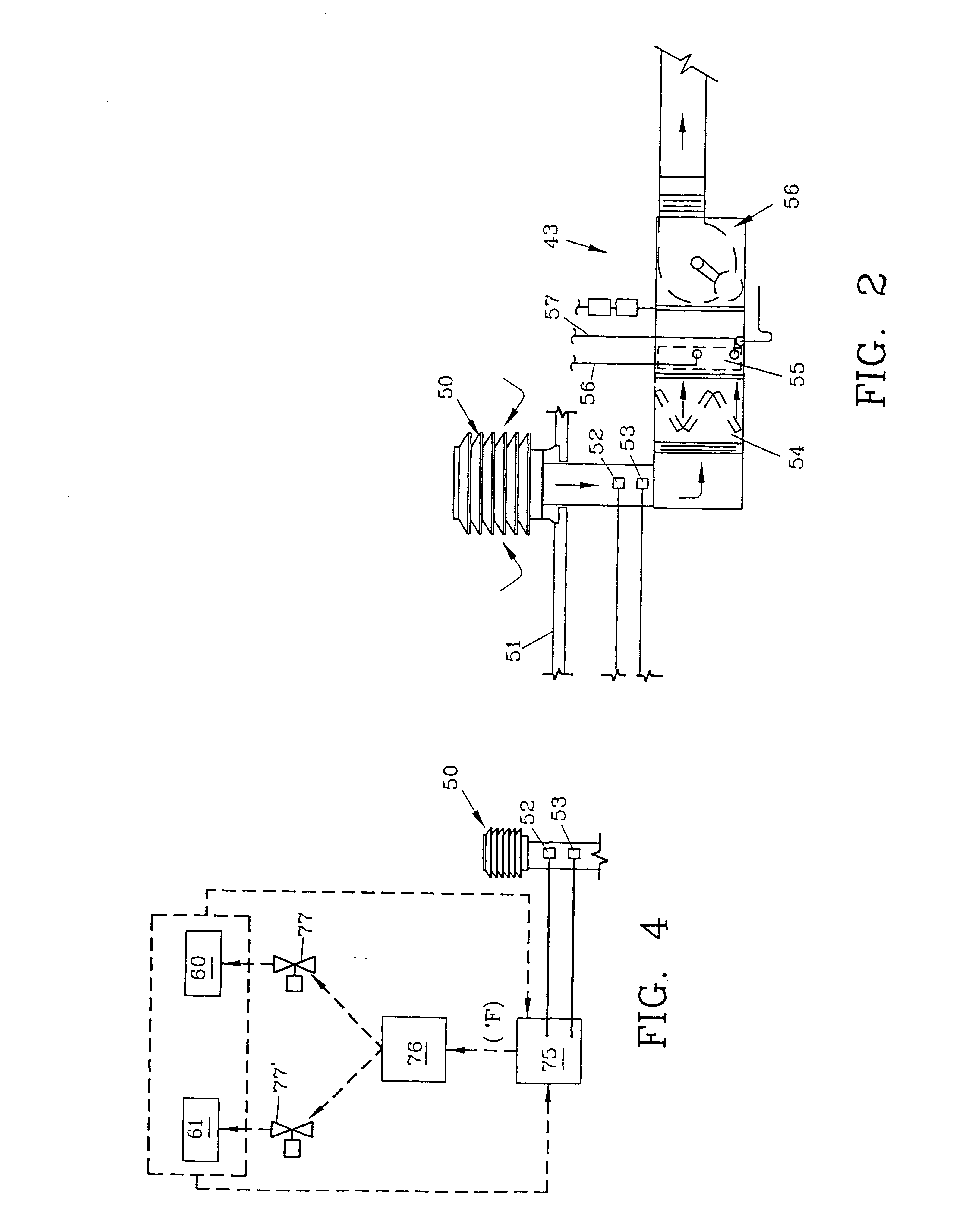
This staging or compressor control maximizes the moisture removal from the outside air before it is brought into the conditioned air space, allowing peak efficiency of the refrigeration furniture cases with the least amount of HVAC (compression) horsepower expended for a minimum energy consumption. For example, in stage 2 the smaller compressor which may be a 71 / 2 horsepower compressor would operate while the larger, 15 horsepower compressor does not. Any wet bulb temperature below 57.2.degree. F. would freeze the evaporator coils of the HVAC systems so any wet bulb temperature above that set point (57.2.degree. F.) would activate stage 2, creating a minimum suction temperature of 32.degree. F. If the wet bulb temperature increases, the microprocessor will cycle the compressors on and off into the four stages as required. A time delay circuitry (set at 30 minutes) is employed whereby the staging will not be subjected to radical staging changes.

Problems solved by technology

Fresh outside air brought into a building through the HVAC system contains moisture which impacts the efficiency and expense of operating internal refrigeration systems (refrigeration furniture such as food display cases and the like).
While such efficiency loss and operational expense may be nominal in homes or small offices, in larger commercial establishments moisture can severely impact refrigeration furniture and greatly increase the operational cost in a relatively short period of time.
As all refrigeration furniture utilizes evaporator coils, such coils can "freeze" or form ice on the outside surfaces due to the humidity present.
When a coil is "frozen", the refrigeration circuit is ineffective and may result in the goods thawing or spoiling.
Even in instances where the goods are not severely damaged, the operation of the refrigeration furniture is lessened, causing high power consumption and increased expense as it operates.

Method used


Image

  • HVAC system and method for conditioning air
  • HVAC system and method for conditioning air
  • HVAC system and method for conditioning air

Examples


Embodiment Construction

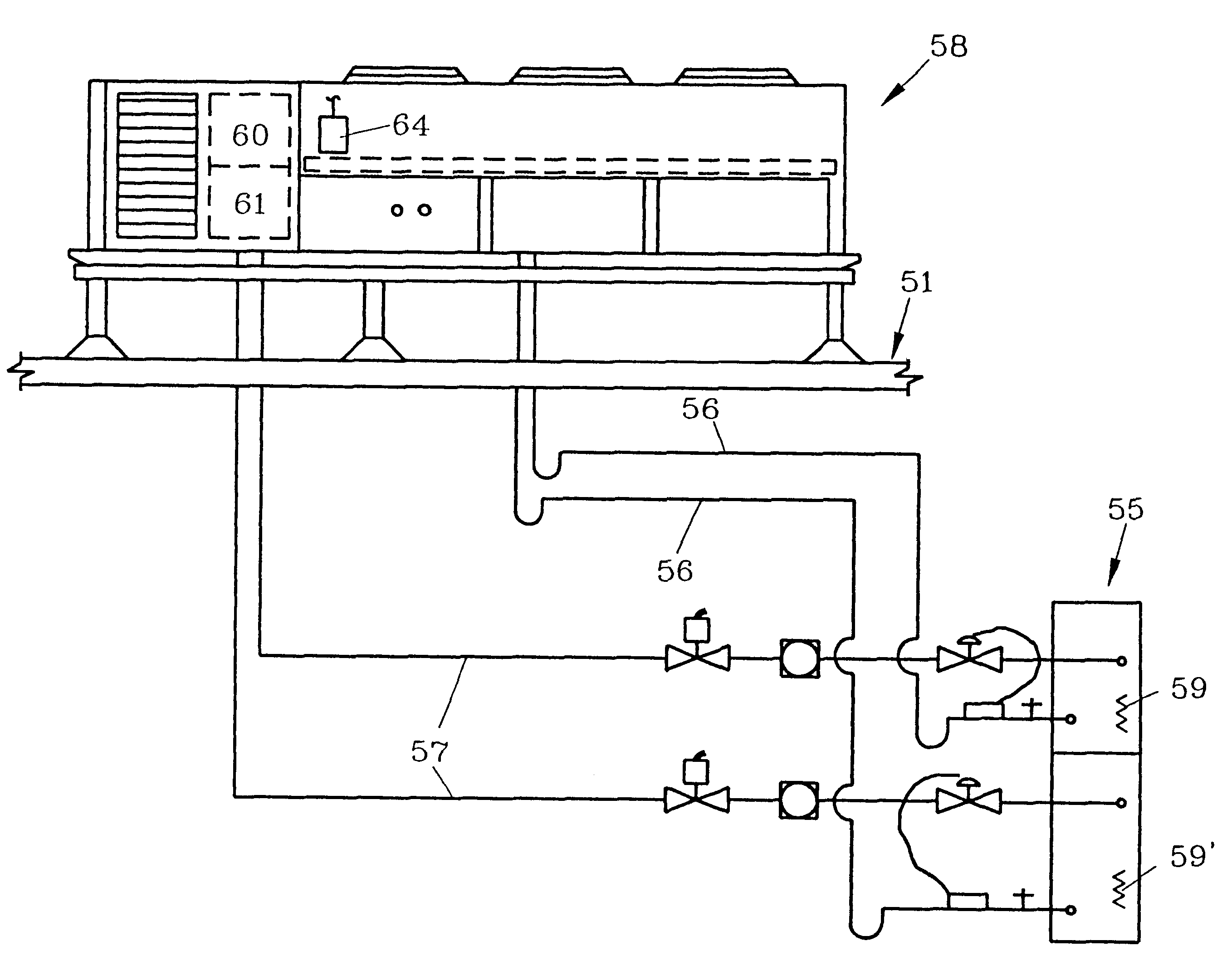
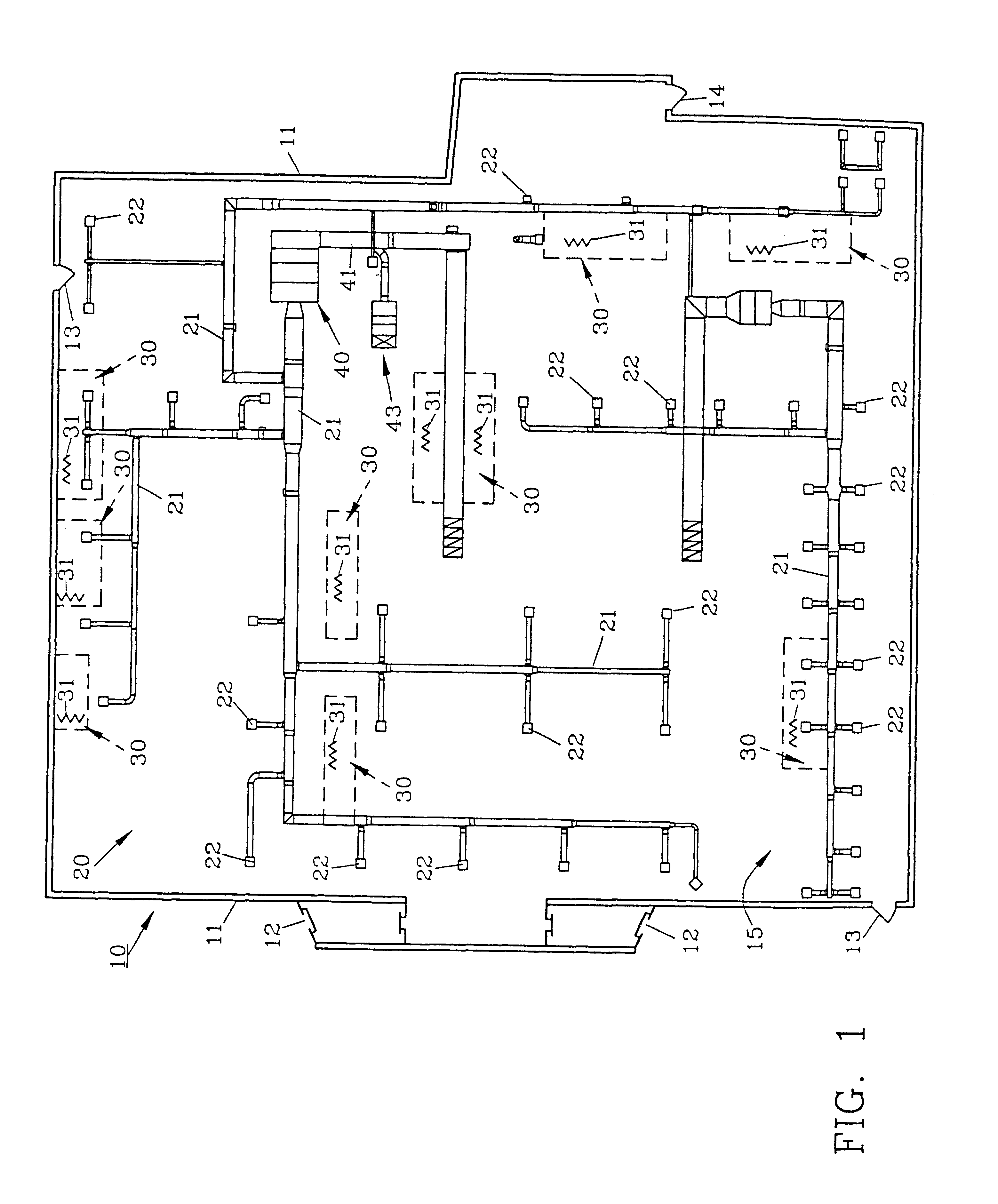
For a better understanding of the invention and its operation, turning now to the drawings, FIG. 1 demonstrates a schematic representation of a typical grocery store 10 with the roof removed to view the contents and components therein. As shown, outside wall 11 surrounds the interior of store 10 having front doors 12, auxiliary doors 13 and a rear door 14. Preferred HVAC system 20 includes conventional air ductwork 21 with diffusers 22 throughout for delivering conditioned air within store 10.

As is typical, grocery store 10 includes a series of refrigerated furniture cases 30 (shown in dotted lines) which may be both the low temperature (0.degree. F.) and medium temperature (32-0.degree. F.) types for displaying respectively, frozen foods, meat and dairy products. Nine such furniture cases are shown in FIG. 1 although the exact number will vary depending on the size of the store and the demands of its customers.

Each refrigerant furniture case 30 includes evaporator cooling coils 31 ...


PUM


Abstract

Outside air is treated to remove moisture before it enters the conditioned air space of a store or other building containing refrigeration furniture. The sensible air temperature and relative humidity measurements are taken to allow microprocessor calculations of the wet bulb temperature. A pair of unequal sized compressors of the HVAC system are then cycled in stages for peak efficiency and minimum compressor horsepower usage for low cost operation and minimal energy consumption both of the HVAC system and the refrigeration furniture. The wet bulb temperature is converged by the microprocessor which iterates a known polynomial approximately every 6 seconds to derive the wet bulb temperature. A time delay circuitry set at approximately 30 minutes prevents unnecessary staging of the compressors.

Description

The invention herein pertains to conditioning air for a building and particularly pertains to removing moisture from the outside air to improve the efficiency of refrigeration systems therein.DESCRIPTION OF THE PRIOR ART AND OBJECTIVES OF THE INVENTIONFresh outside air brought into a building through the HVAC system contains moisture which impacts the efficiency and expense of operating internal refrigeration systems (refrigeration furniture such as food display cases and the like). While such efficiency loss and operational expense may be nominal in homes or small offices, in larger commercial establishments moisture can severely impact refrigeration furniture and greatly increase the operational cost in a relatively short period of time. This is particularly true in businesses such as shops and stores which require relatively high tonnage HVAC systems such as in a typical grocery store of 38,000 square feet, having a 50-60 tonnage HVAC system operating under standard conditions.An...

Claims


Application Information

Patent Timeline
IPC IPC(8): F24F11/00F25B49/02
CPCF24F11/0076F24F2011/0013F24F2011/0016F25B49/022F25B2400/0751F25B2400/22F25B2600/0251F24F2110/12F24F2110/22F24F11/70F24F11/46F24F11/86
Inventor MCNAMARA, PATRICK J.CLARK, WILLIAM E.
Owner TRS SESCO LLC
Learn More