

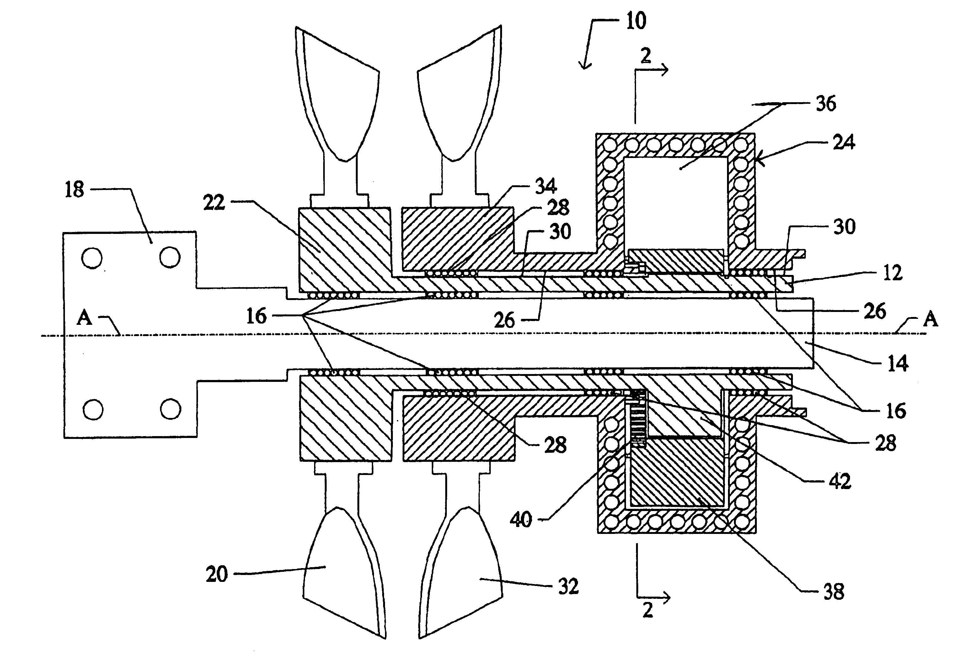
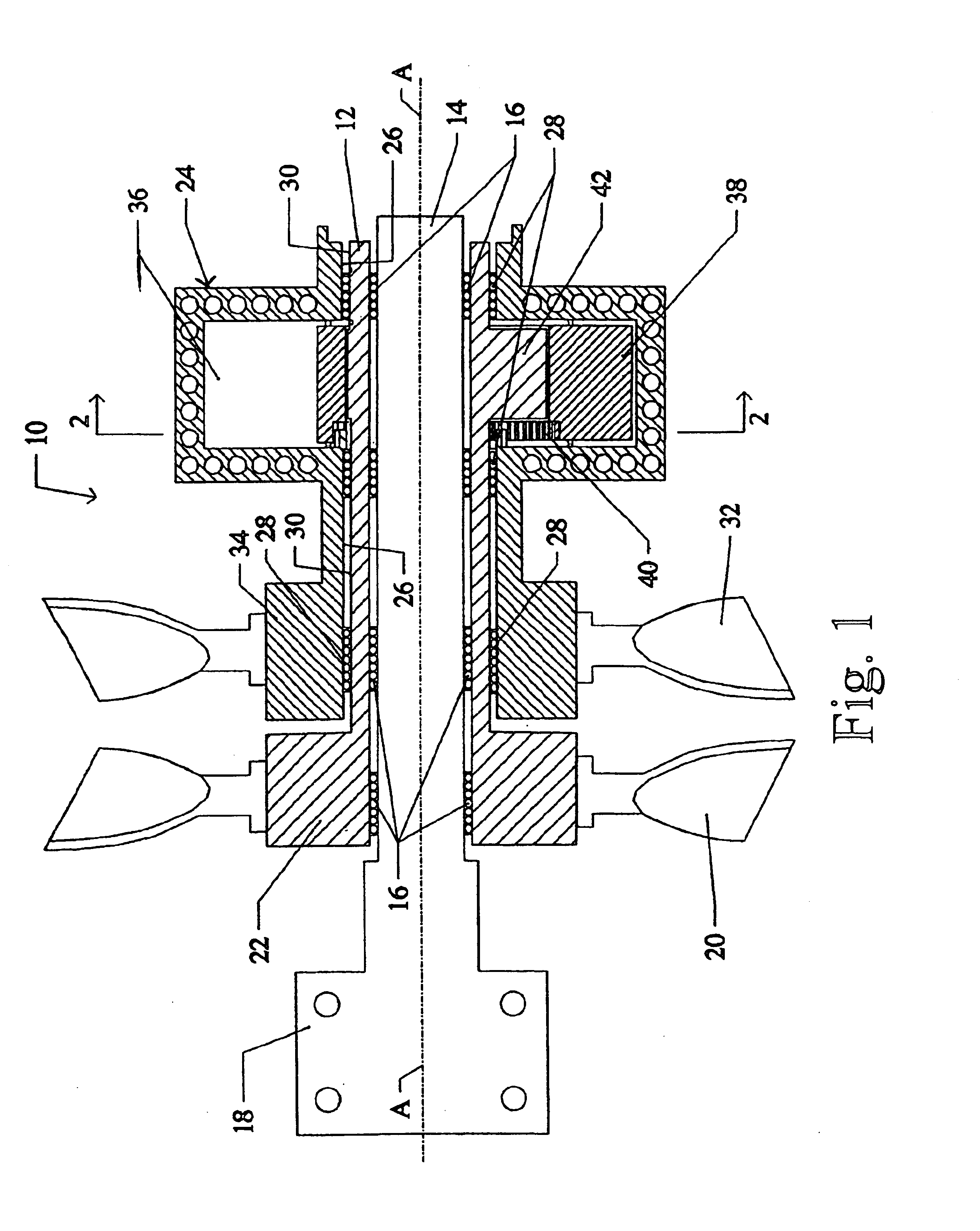
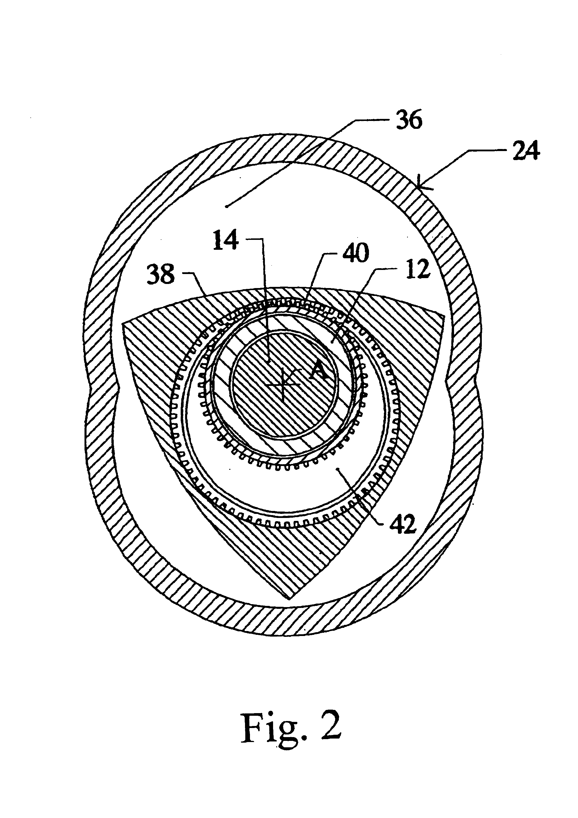
Rotary engine with counter-rotating housing and output shaft mounted on stationary spindle
a technology of counter-rotating and output shaft, which is applied in the direction of liquid fuel engine components, wind motors with parallel air flow, rotary piston liquid engines, etc., can solve the problems of inability to meet the needs of the user, etc., to achieve stable and safe journaling
- Summary
- Abstract
- Description
- Claims
- Application Information
AI Technical Summary
Benefits of technology
Problems solved by technology
Method used
Image

Examples
Embodiment Construction
This invention lies in the recognition that an engine with an output shaft having a longitudinal inner cavity can be utilized to facilitate the counter-rotation of dual propellers mounted on the engine's shaft and block, respectively. This aspect of the invention can be achieved advantageously by a rotary-piston engine as well as by a turbine engine with a hollow output shaft journaled around a support spindle in a support structure. Accordingly, the invention is described mainly with reference to a rotary-piston engine, but the term rotary engine is intended to refer to a turbine engine as well.
Another aspect of the invention resides in the recognition that rotary engines, in the absence of an axial crankcase, provide an opportunity for lubrication of all internal parts of the engine without accumulation of oil and the corresponding centrifugal-force effects imposed by the rotation of the engine housing. Lubrication can be achieved by the use of porting from the stationary structur...
PUM
 Abstract
Description
Claims
Application Information