Submerged flowline termination at a single point mooring buoy

a flowline and mooring buoy technology, applied in the direction of passenger handling apparatus, special-purpose vessels, packaged goods types, etc., can solve the problems of submerged product swivel, fatigue damage, fatigue failure, etc., and achieve the effect of removing wave-induced coupling

Inactive Publication Date: 2004-07-20
SOFEC
View PDF13 Cites 18 Cited by
  • Summary
  • Abstract
  • Description
  • Claims
  • Application Information

AI Technical Summary

Benefits of technology

A primary object of the invention is to provide a product transfer system from a FPSO or platform via a pipeline (either rigid or flexible) to a mooring and transfer buoy such as a CALM or SALM and then to a shuttle tanker while substantially eliminating coupling of wave induced motions of the buoy with the end of the pipeline.
Another object of the invention is to provide a product transfer system which decouples a submerged pipeline from a surface offloading buoy and its wave induced motions, thereby reducing fatigue damage to the pipeline.
Another object of the invention is to provide a product transfer arrangement that allows for optimizing of pipeline diameter and buoyancy, because improved fatigue resistance allows for greater variability in the configuration of the submerged pipeline.
Another object of the invention is to support a flowline in a way that decouples the SALM or CALM buoy from the flowline with a resulting low fatigue damage to the flowline at the lowest practical cost.
The objects identified above along with other advantages and features are provided in the invention embodied in a product transfer system by which a rigid or flexible pipeline from a FPSO or platform or the like extends in the sea above the seabed for about a nautical mile where it terminates close to and below a SALM or a CALM buoy, and where it is fluidly coupled to a flexible hose at a coupling arrangement. The coupling is supported by the SALM or CALM below the wave kinematics zone by an elastic flowline mooring leg or motion compensator. The elastic flowline mooring leg extends generally vertically downward from the SALM or CALM buoy and is anchored at its lower end at a short distance from the connector. A flexible member such as a chain is connected between the lower end of the vertical elastic mooring leg and the connector. The elastic mooring leg reduces the coupling of the vertical motion of the SALM or CALM buoy to the pipeline end.

Problems solved by technology

A problem exists in connecting the end of the pipeline directly to the SPM buoy, because as the buoy moves up and down and side to side, the end of the pipeline moves with it, and as a result is subject to fatigue failure.
The problem identified above is inherent in prior offloading deep water SPM buoys which have pipelines attached directly to and supported from a CALM buoy for example.
The pipelines are directly coupled to the CALM buoy such that motions of the CALM buoy are also directly coupled to the pipeline with resulting fatigue damage.
The submerged CALM buoy, although beneath the dynamic zone of the sea and thereby isolates the steel pipeline connection to the CALM from substantial vertical motion, nevertheless is disadvantageous in that a submerged product swivel is required.
While eliminating a certain level of coupling of wave induced forces to the end of the rigid steel flowline which extends from a production and / or storage facility (FPSO or platform), nevertheless, a sufficient degree of coupling still exists to create a fatigue problem, and possible failure, for the pipeline.

Method used


Image

  • Submerged flowline termination at a single point mooring buoy
  • Submerged flowline termination at a single point mooring buoy
  • Submerged flowline termination at a single point mooring buoy

Examples


Embodiment Construction

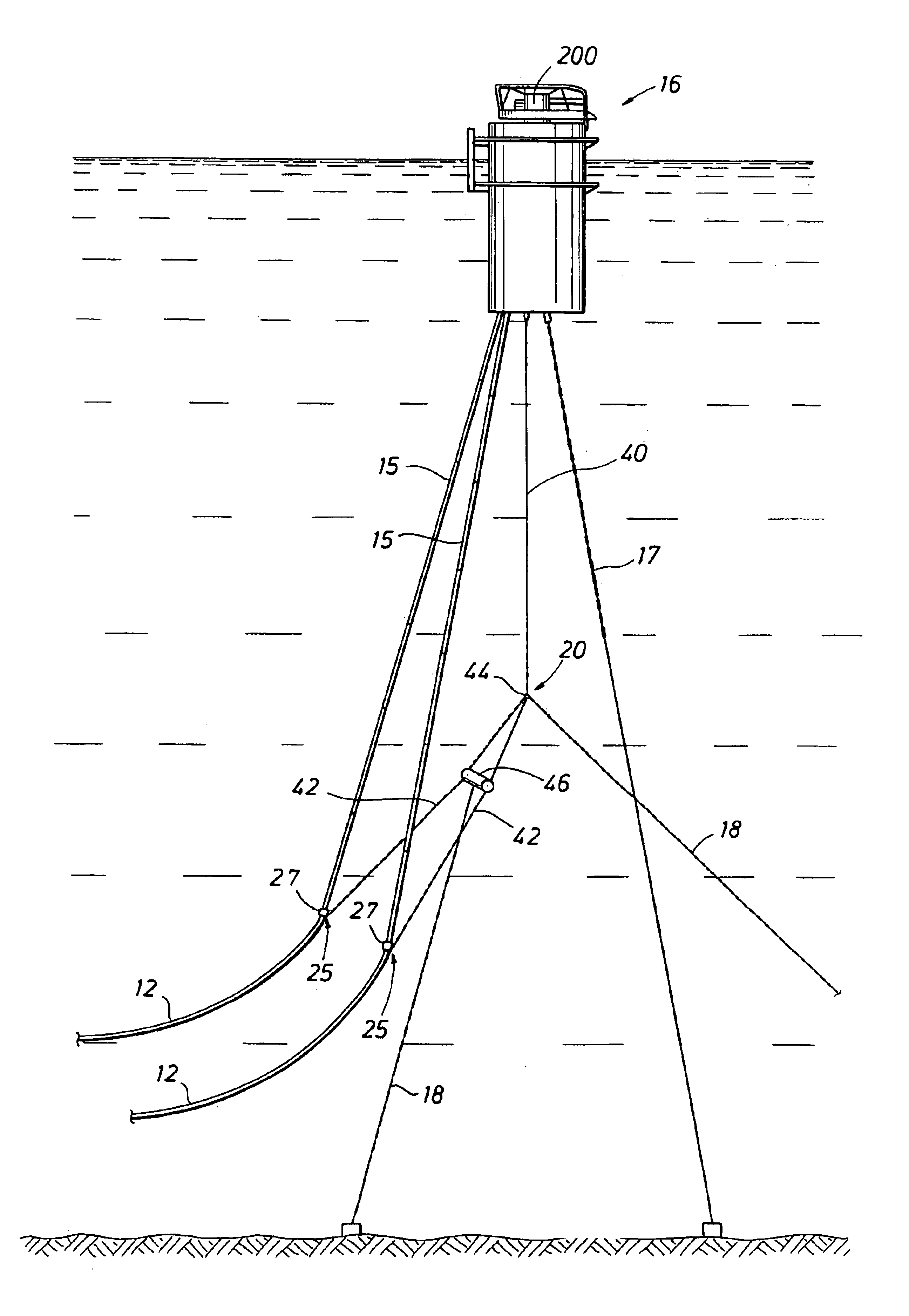
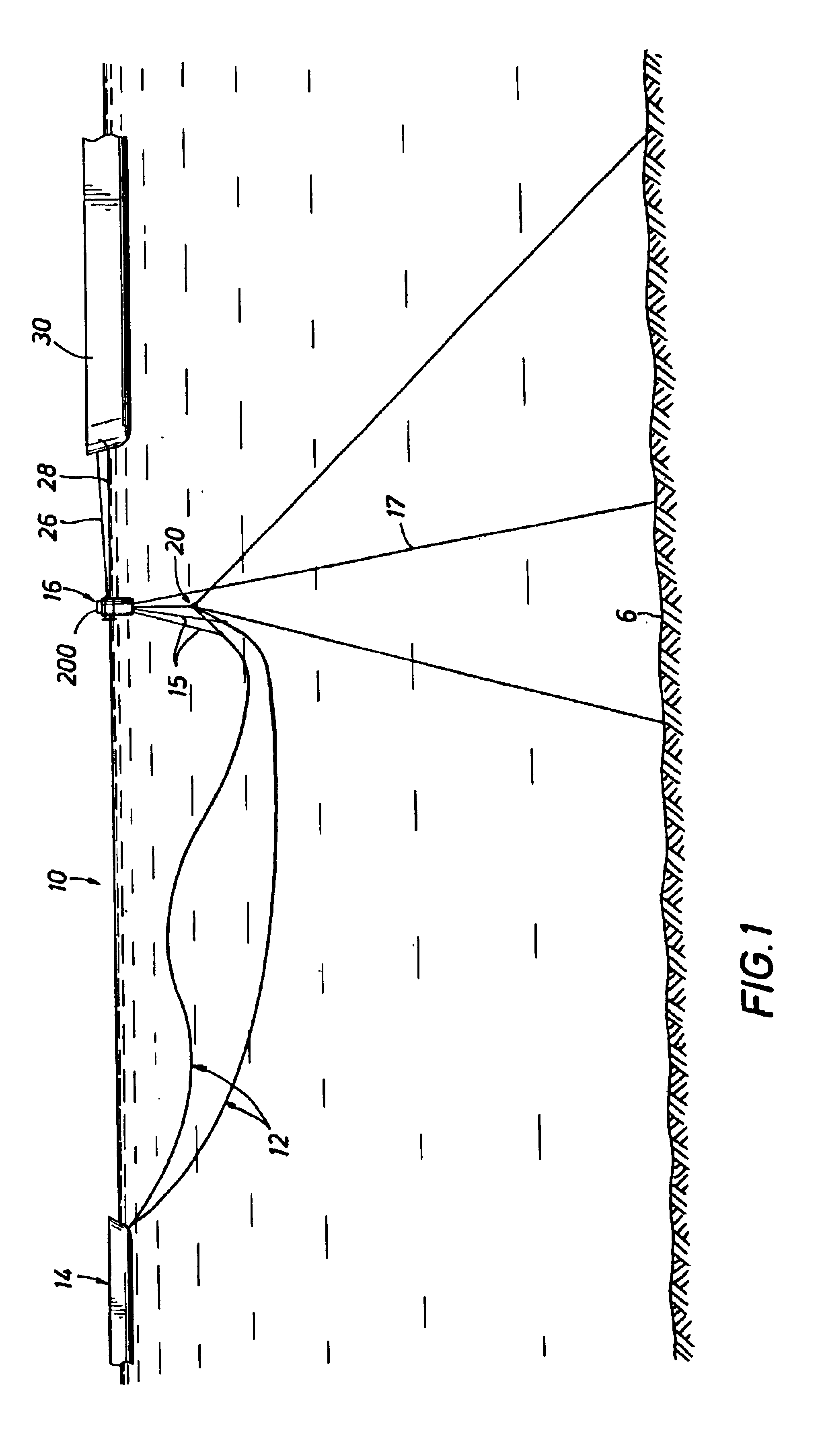
The mooring and fluid transfer arrangement of this invention generally concerns deep water hydrocarbon offloading from offshore production platforms, either fixed (e.g., Jacket structures), or floating (e.g., FPSOs, Semi-submersibles, or Spars). Conventional offloading arrangements provide a single offloading buoy located approximately two kilometers away from the platform, with a submerged flexible or steel pipeline(s) connected between them. With the prior arrangements, the surface offloading buoy requires a large displacement to support the submerged pipeline(s) and their product. Because of its size, the offloading buoy is subject to motions in response to the wave environment. These wave-frequency motions are coupled to the pipeline and affect its dynamic response, leading to fatigue damage to the pipeline over time.

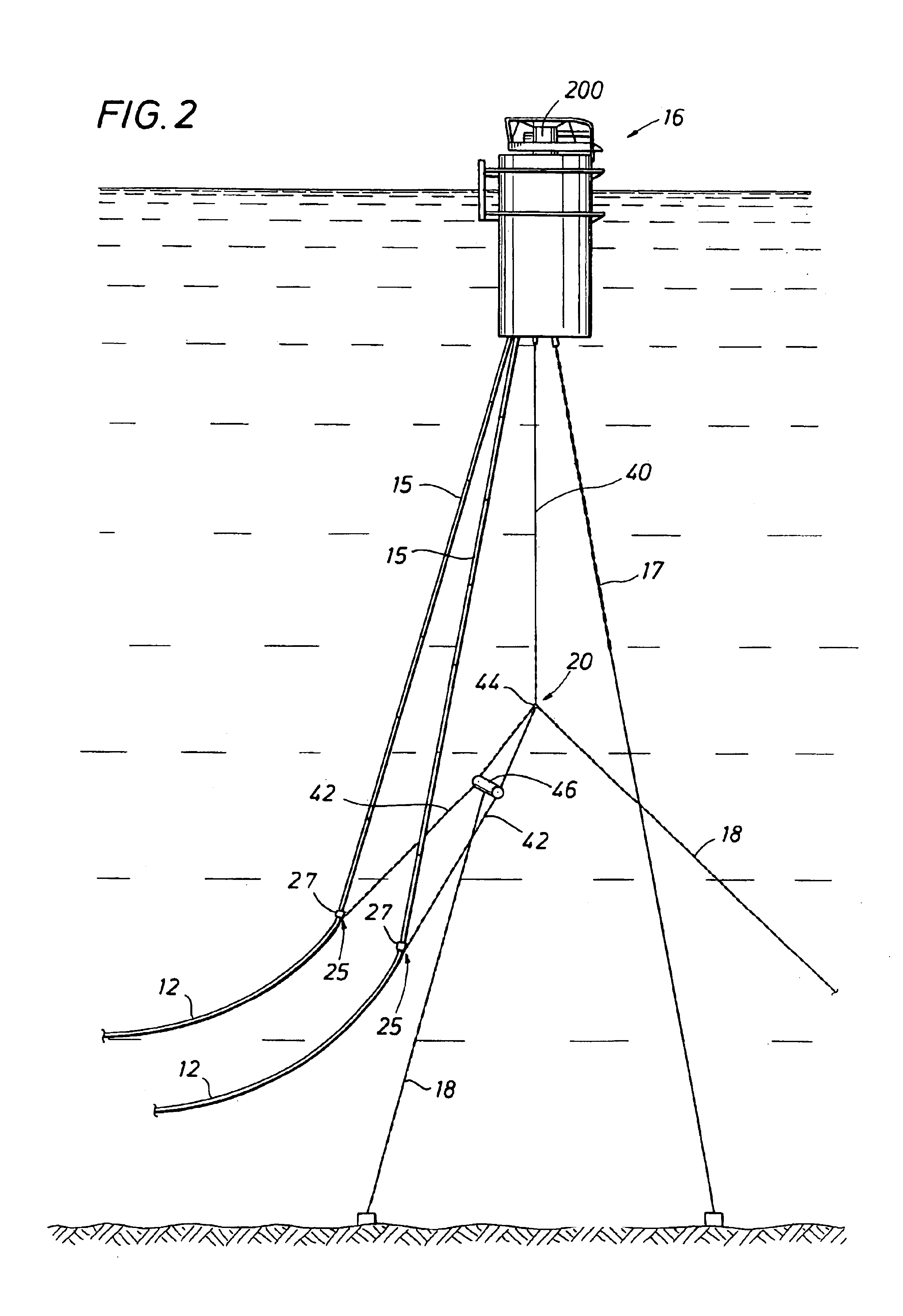
The connector arrangement of this invention between a pipeline and a flexible hose is supported by an elastic coupling which effectively eliminates the fatigue dama...


PUM

PropertyMeasurementUnit
depthsaaaaaaaaaa
depthaaaaaaaaaa
flexibleaaaaaaaaaa

Abstract

A submerged connection assembly for connecting an end of a pipeline to a flexible hose that runs to a SPM buoy including an elastic suspension arrangement between the SPM buoy and the connection assembly.

Description

1. Field of the InventionThis invention relates generally to an offshore loading system such as a CALM or SALM which serves as a single point mooring (SPM) for a shuttle tanker or the like and a product transfer system for transferring hydrocarbon product via an associated product flowline arrangement between a production and / or storage facility such as a platform or FPSO and the SPM to the shuttle tanker.2. Description of Prior ArtIn deep water operations, certain operational considerations make it desirable to offload hydrocarbons from a production and / or storage facility by running a pipeline to an offshore loading system, such as a CALM or SALM (i.e., a SPM buoy) buoy, where a shuttle tanker may be moored and connected to a loading hose for filling its tanks with crude oil. Deep water installations, e.g., in depths greater than about 1000 feet, require that the pipeline be suspended between the production and / or storage facilities, such as a platform or FPSO and the SPM buoy rat...

Claims


Application Information

Patent Timeline
Patent Type & Authority Patents(United States)
IPC IPC(8): B63B22/02B63B27/00B63B22/00B63B27/24
CPCB63B22/026B63B27/24B63B27/34
Inventor FONTENOT, WILLIAM L.ZIMMERMANN, CHARLES A.
Owner SOFEC
Why Eureka
Try Eureka