Carbon nanostructures and methods of preparation

a carbon nanotube and nanostructure technology, applied in the field of carbon nanotubes and methods of preparation, can solve the problems of short (100 nm) nanotubes, defects in carbon nanotubes, and conventional methods of making multi-walled nanotubes via arc discharg

Inactive Publication Date: 2004-07-20
CHANG ROBERT P H
View PDF4 Cites 85 Cited by
  • Summary
  • Abstract
  • Description
  • Claims
  • Application Information

AI Technical Summary

Benefits of technology

It can also be an object of the present invention to provide a method for preparation of carbon nanostructures of the type described herein, having enhanced and / or superior structural or mechanical properties, including but not limited to overall length and strength.
In another aspect of the present invention, another method of synthesizing carbon nanotubes in a continuous way is provided by using the arc-furnace shown in FIG. 16. Carbon precursors are fed into a tubing which they are transported into the arc-furnace zone(s) for processing. There can be a series of arc-furnaces in tandem to improve the processing efficiency. The arc-furnace was the same as that described in Example 7 except that the electrodes are tubular and constructed of metal, for example tungsten. The arc-furnace is again powered by a direct current supply. After going through the heating zone(s), the carbon nanotubes are extracted from the opposite end. The feeding of the precursors can be by a mechanical pusher or pressurized gas.

Problems solved by technology

However, conventional methods of making multi-walled nanotubes via arc discharge do not easily lend themselves to large scale production.
Various complexities relating to feed rates, competing side reactions and product purity, among others, tend to detract from the wide-spread applicability and acceptance of this approach.
In so doing, defects are generated in the carbon nanotubes.
However, only short (<100 nm) nanotubes have been made by annealing fullerene soot.
The complexity of the arc process makes it very difficult to study the formation of these materials or draw any conclusions regarding conditions necessary to maximize optimal growth and / or yield.
There are a considerable number of problems and deficiencies associated with carbon nanostructures of the prior art, with most such shortcomings resulting from the current methods of preparation.

Method used


Image

  • Carbon nanostructures and methods of preparation
  • Carbon nanostructures and methods of preparation
  • Carbon nanostructures and methods of preparation

Examples


example 1

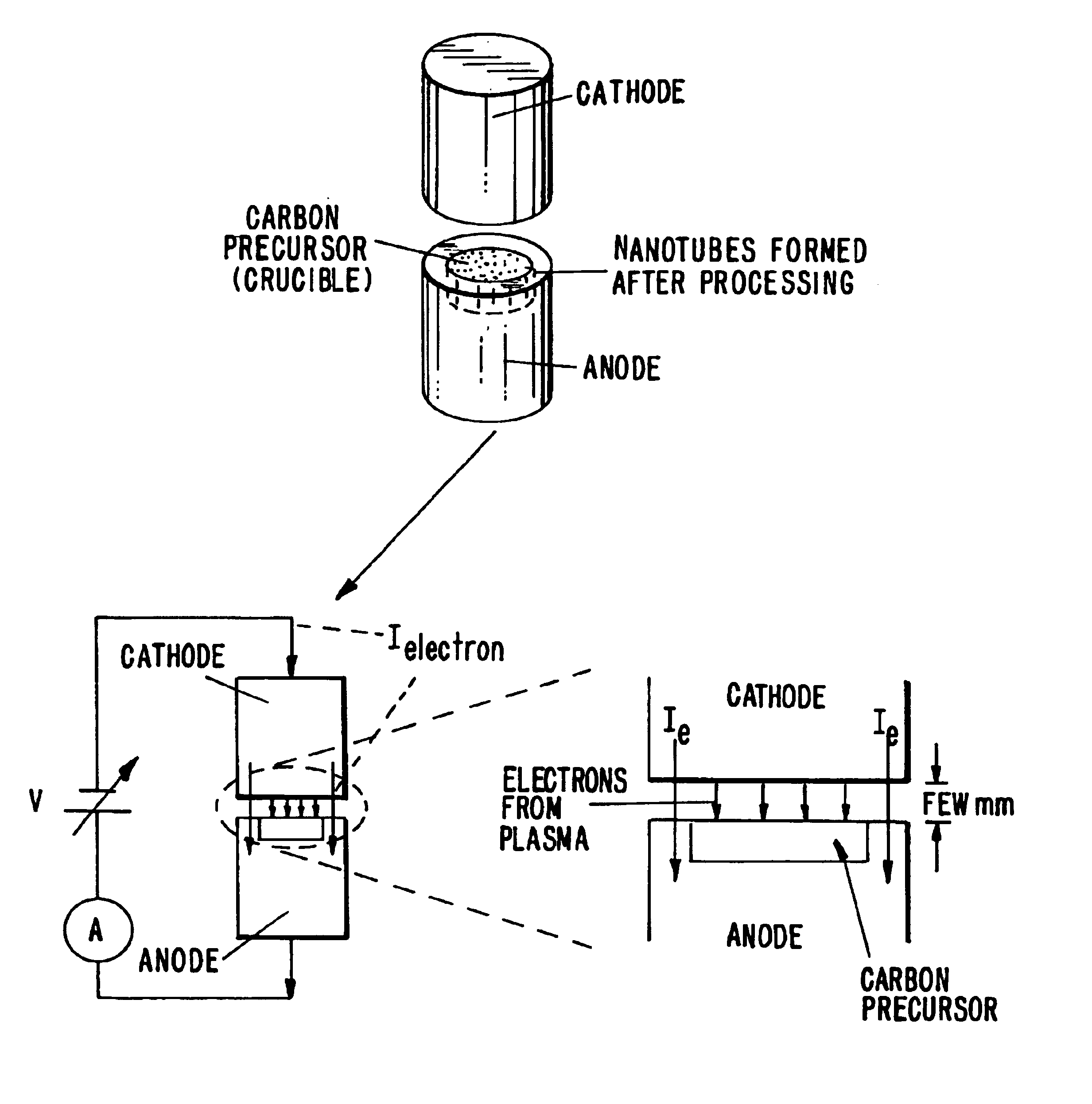
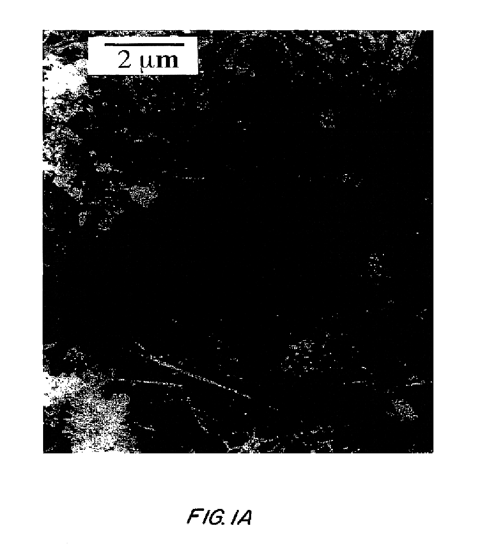
Fullerene soot was made by the arc evaporation of graphite at 450 Torr of He, then activated in a flowing CO.sub.2 atmosphere at 850.degree. C., which increased its surface area. The soot was then mixed with varying amounts (0-20 wt%) of amorphous boron and annealed under flowing He in a graphite resistance furnace to 2200-2400.degree. C. Boron was added to accelerate the assembly of fullerene soot by acting as a fast diffuser in the basal planes of graphite. Annealing fullerene soot without boron provided polyhedral carbon particles as in previous experiments. In comparison, analysis of the annealed fullerene soot mixed with boron showed nanotubes with length much longer than 0.5 .mu.m (FIG. 1A).

example 2

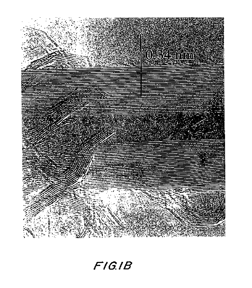
High resolution micrographs (FIGS. 1B and 1C) show that the tubes of example 1 made using boron were similar to multiwalled nanotubes made using an arc discharge, with occasional kinks in the nanotube (FIG. 1C). However, some nanotube ends were not completely closed and had disordered carbon around the tip (FIG. 1B). The disordered carbon at the tip indicates that growth was frozen either when the furnace was cooling or when the local carbon supply was exhausted. The inner shells of nanotubes were occasionally closed off, as in some nanotubes produced in an arc discharge (FIG. 1C). Polyhedral graphitic nanoparticles were the majority of the products (FIG. 1A).

example 3

The applicability of this invention was extended to other disordered carbon materials: for example, ball milled graphite and sucrose carbon. While heat treatment of ball milled graphite with boron (FIG. 2) did not produce any nanotubes (only bent and tangled graphitic sheets and closed particles are found), annealing sucrose carbon with boron does produced multiwalled carbon nanotubes (FIG. 3). Open nanotubes were also seen in these experiments (FIG. 3A). The overall yield of nanotubes when annealing sucrose carbon was low. These experiments show that it is possible to make nanotubes by controlling the heat treatment of common and inexpensive organic materials. Also, some nanotubes might be attached to graphitic particles as shown in FIG. 3B. These larger graphitic particles might act as nucleation sites for nanotubes. However, if this were the case, every heat treatment sample should have nanotubes because after heat treatment all samples had similar graphitic particles. Consequent...


PUM

PropertyMeasurementUnit
lengthaaaaaaaaaa
pressureaaaaaaaaaa
temperatureaaaaaaaaaa

Abstract

An electric arc furnace and method for forming tubular carbon nanostructures comprising a first electrode (cathode) and an a second electrode (anode) opposite the first electrode, sources of voltage (V) and current (A) to create charged particles (Ie) and produce an arch between the electrodes, a source of a gas to surround the arc, and a source of carbon precursor positioned adjacent the anode and within the arc, wherein the arc is maintained at a pressure and high temperature for a time sufficient to heat the carbon precursor to form carbon nonotubes upon the anode.

Description

Since the discovery of carbon nanotubes (S. Iijima, Nature 354, 56 (1991); T. W. Ebbesen and P. M. Ajayan, Nature 358, 220 (1992)) there have been many applications for such materials. Their size and high aspect ratios leads to possible use as electron emitters for flat panel displays (Q. H. Wang, A. A. Setlur, J. M. Lauerhaas, J. Y. Dai, E. W. Seelig, and R. P. H. Chang, Appl. Phys. Lett. 72, 2912 (1998)) and AFM / STM probes. (H. Dai, J. H. Hafner, A. G. Rinzler, D. T. Colbert, and R. E. Smalley, Nature 384, 147 (1996).) In addition, the reduced number of defects in nanotubes could make them the ultimate carbon fiber in terms of strength and stiffness. (M. M. J. Treacy, J. M. Gibson, and T. W. Ebbesen, Nature 381, 678 (1996); E. W. Wong, P. E. Sheehan, and C. M. Lieber, Science 277, 1971 (1997).)CARBON NANOTUBESCarbon tubules and related nanostructures are typically prepared using standard arc-discharge techniques. Generally, the discharge is in a reaction vessel through which an in...

Claims


Application Information

Patent Timeline
Patent Type & Authority Patents(United States)
IPC IPC(8): C01B31/00C01B31/02B01J19/08
CPCB01J19/088B82Y30/00B82Y40/00C01B31/0213C01B31/0226C01B31/0233C01B31/024B01J2219/0809B01J2219/083B01J2219/0871B01J2219/0886B01J2219/0894C01B2202/06Y10S977/742Y10S977/90Y10S977/842Y10S977/743C01B32/154C01B32/16C01B32/162C01B32/164
Inventor CHANG, ROBERT P. H.
Owner CHANG ROBERT P H
Why Eureka
Try Eureka