Compact fuel gas reformer assemblage

a fuel gas reformer and compact technology, applied in the direction of indirect heat exchangers, electrochemical generators, lighting and heating apparatus, etc., can solve the problems of undesirably large and heavy reformer assemblies

Inactive Publication Date: 2004-08-10
INT FUEL CELLS
View PDF9 Cites 75 Cited by
  • Summary
  • Abstract
  • Description
  • Claims
  • Application Information

AI Technical Summary

Benefits of technology

It is therefore an object of this invention to provide an improved heat exchange relationship between a burner gas stream component and a process fuel gas stream component in a hydrocarbon fuel gas reformer assembly which is suitable for use in a fuel cell power plant.

Problems solved by technology

This need for a large catalyst bed and heat transfer surface area, when met by using catalyst-coated pellets in tubular reformers, results in undesirably large and heavy reformer assemblies.

Method used


Image

  • Compact fuel gas reformer assemblage
  • Compact fuel gas reformer assemblage
  • Compact fuel gas reformer assemblage

Examples


first embodiment

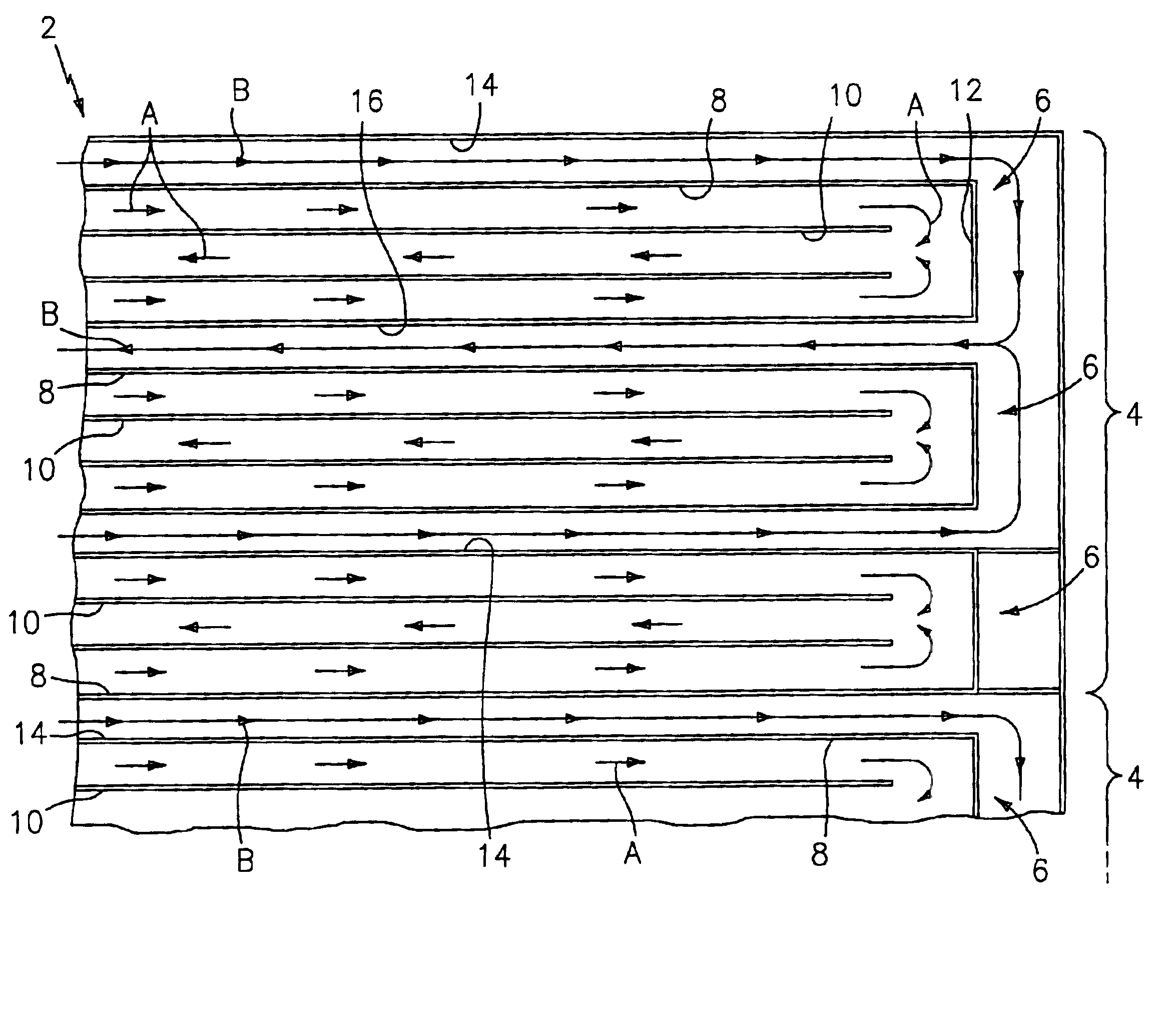
Referring now to the drawings, there is shown in FIG. 1 a fragmented schematic view of a reformer assembly which reformer assembly is denoted generally by the numeral 2, and which includes adjacent repeating burner gas-process gas modules which are denoted generally by the numeral 4. Each of the modules 4 shown in FIG. 1 includes a plurality of process gas components 6, and each of the process gas components 6 includes a pair of process gas inlet passages 8 which are sandwiched around a regenerator process gas outlet passage 10. The direction of process gas flow through the passages 8 and 10 is indicated by arrows A. The process gas passages 8 and 10 are interconnected by a flow-reversal manifold 12. The walls of the process gas passages 8, 10 and 12 are provided with a process gas reforming catalyst coating, as described in the aforesaid '578 patent.

It will be noted that in the reformer design embodiment shown in FIG. 1, two of the process gas reforming components 6 are provided wi...

third embodiment

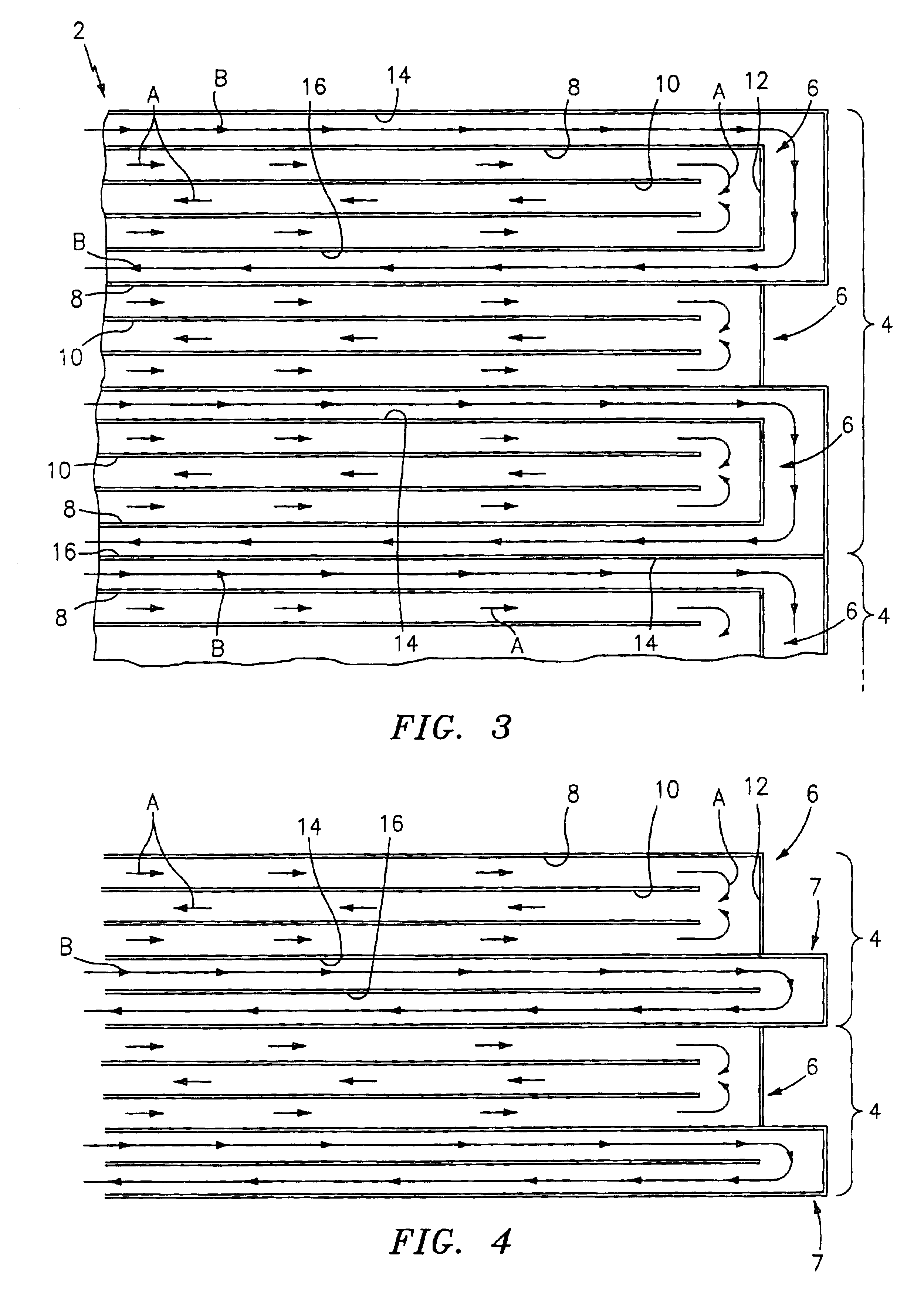
Referring now to FIG. 3, there is shown a reformer assembly 2 which is formed in accordance with this invention. In the fragmented illustration of this embodiment of the invention, there are shown seven process gas reforming passages 8. Of the seven process gas reforming passages 8 shown, four are disposed in the more desirable co-flow relationship with adjacent burner gas passages 14; and the remaining three reforming passages 8 are disposed in the acceptable counter-flow relationship with the adjacent burner gas passages 14. It will be noted that in the embodiment shown in FIG. 3, there is still a majority of the co-flow gas passage relationships, and a minority of the counter-flow gas passage relationships.

Referring now to FIG. 4, there is shown yet another embodiment of a reformer assembly 2 which is formed in accordance with this invention. In the fragmented illustration of this embodiment of the invention, there are shown two modules 4, each of which includes a process gas ref...


PUM

PropertyMeasurementUnit
temperatureaaaaaaaaaa
volumeaaaaaaaaaa
temperaturesaaaaaaaaaa

Abstract

A fuel gas reformer assemblage for use in a fuel cell power plant is formed from a composite plate assembly which includes spaced-apart divider plates with columns of individual gas passages. The reformer assemblage is constructed from a series of repeating sub-assemblies, each of which includes a core of separate regenerator / heat exchanger gas passages. The core in each sub-assembly is sandwiched between a pair of reformer gas passage skins, which complete the assembly. Adjacent reformer gas / regenerator / reformer gas passage sub-assemblies in the composite plate assembly are separated from each other by burner gas passages. The regenerator / heat exchanger gas passages and the reformer gas passages in each sub-assembly are connected by gas flow reversing manifolds which form a part of each sub-assembly. The fuel gases flow in one end of the assemblage, through the reformer gas passages, and then reverse their direction of flow in the return manifolds so as to exit the reformer assemblage through the regenerator gas flow passages. The burner gases flow in one end of the reformer assemblage and out the other end. The walls of the burner and reformer gas flow passages are selectively catalyzed after the assemblage has been constructed.

Description

DESCRIPTION1. Technical FieldThis invention relates to a light weight and compact fuel gas steam reformer design which is formed from a plurality of repeating gas flow modules. More particularly, this invention relates to a fuel gas steam reformer design which provides improved heat transfer between a burner gas stream and a fuel gas stream being reformed.2. Background ArtFuel cell power plants include fuel gas steam reformers which are operable to catalytically convert a fuel gas, such as natural gas, into hydrogen and carbon dioxide. The conversion involves passing a mixture of the fuel gas and steam through a catalytic bed which is heated to a reforming temperature of about 1,250.degree. F. to about 1,600.degree. F. Catalysts typically used are nickel catalysts which are deposited on alumina pellets. A typical reformer will consist of a plurality of reaction tubes which are contained in a housing that is insulated for heat retention. The reaction tubes are heated by burning exces...

Claims


Application Information

Patent Timeline
Patent Type & Authority Patents(United States)
IPC IPC(8): F28D7/12C01B3/38H01M8/06B01J19/24
CPCF28D7/12B01J2219/00186C01B2203/0811C01B2203/82B01J2219/2453C01B3/384B01J2219/2479B01J2219/00157C01B2203/0205B01J2219/2462B01J19/249
Inventor LESIEUR, ROGER R.CIPOLLINI, NED E.FULLER, THOMAS F.
Owner INT FUEL CELLS
Why Eureka
Try Eureka