
Structure and method for pulse telemetry

a technology of pulse telemetry and structure, applied in the direction of pulse technique, survey, borehole/well accessories, etc., can solve the problems of difficult data communication using pressure pulses imparted to drilling fluid, pressure fluctuations, and significant noise in the downhole environment, so as to increase data transfer efficiency and shorten the transfer time

Inactive Publication Date: 2004-09-07
HALLIBURTON ENERGY SERVICES INC
View PDF11 Cites 22 Cited by
  • Summary
  • Abstract
  • Description
  • Claims
  • Application Information

AI Technical Summary

Benefits of technology

The patent describes a method and system for improving data transfer efficiency in drilling systems. The method involves selectively splitting data into smaller parts and sending it to the surface in a more efficient way. This is done by creating a larger number of parity values to detect and correct errors. The system includes a drill string with a bottomhole assembly and a transmitter or pulser to create pressure pulses. These pulses are used to transfer information from downhole to the surface. The system also uses a combination of features and advantages to overcome deficiencies of previous devices. Overall, the method and system improve data transfer efficiency and provide better information transmission in drilling systems.

Problems solved by technology

To facilitate the primary purposes, the drilling fluid is pumped into the drill string at high pressure, which causes pressure fluctuations--noise.
Further, the downhole environment generates significant noise in the column of drilling fluid.
These factors make data communications using pressure pulses imparted to the drilling fluid difficult.

Method used


Image

  • Structure and method for pulse telemetry
  • Structure and method for pulse telemetry
  • Structure and method for pulse telemetry

Examples


Embodiment Construction

The problems noted above are solved in large part by a method and related system that increases data transfer efficiency. More particularly, the specification discloses transfer of data by selectively splitting the data into a particular number of bits (for example an eight bit number may be split into two four bit numbers) and sending the data to the surface into smaller groupings, creating shorter transfer times. Further, the specification discloses an increased number of parity values, which may be used to detect and correct errors.

The disclosed devices and methods comprise a combination of features and advantages which enable it to overcome the deficiencies of the prior art devices. The various characteristics described above, as well as other features, will be readily apparent to those skilled in the art upon reading the following detailed description, and by referring to the accompanying drawings.

For a detailed description of the preferred embodiments of the invention, referen...


PUM


Abstract

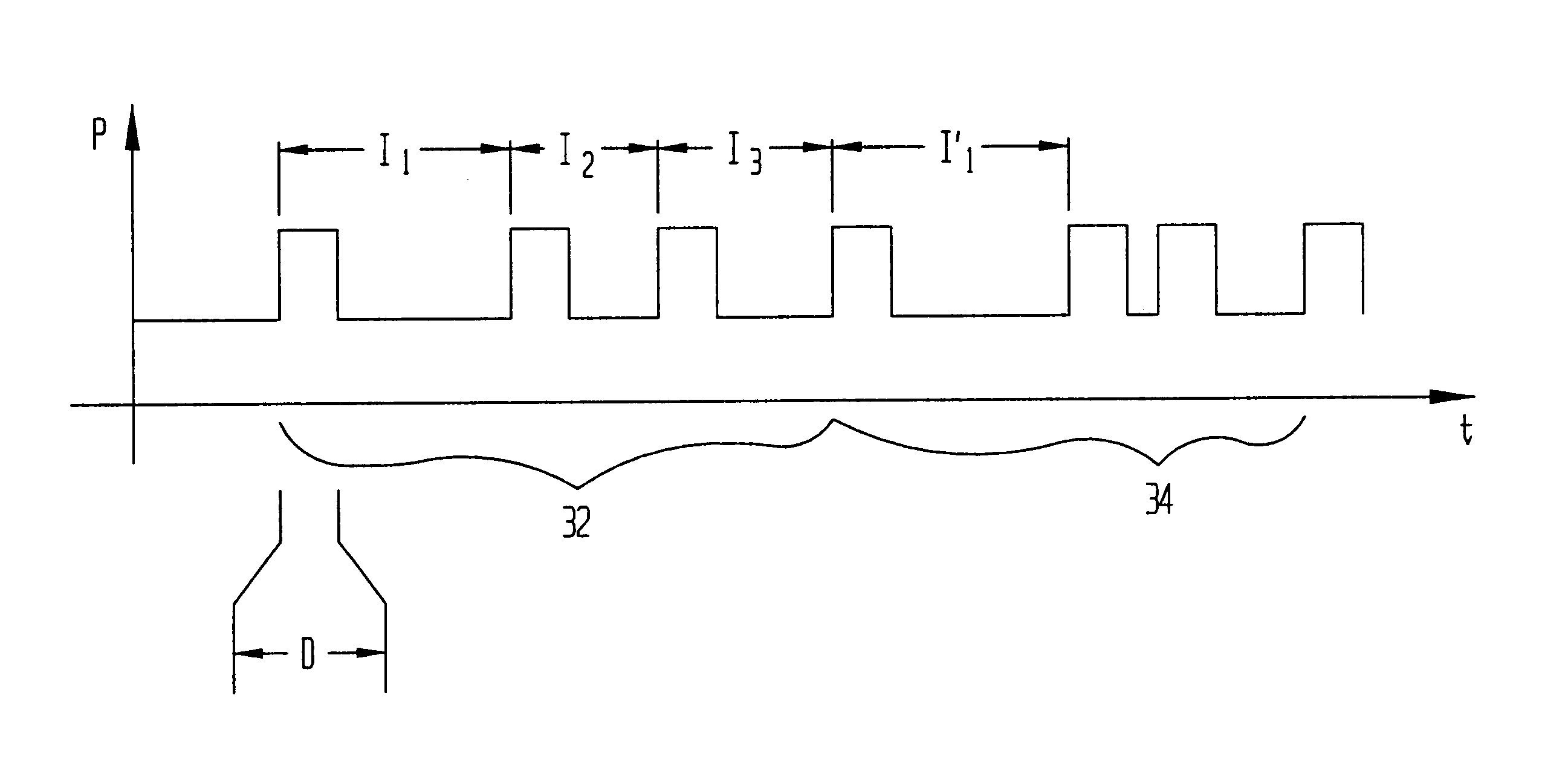
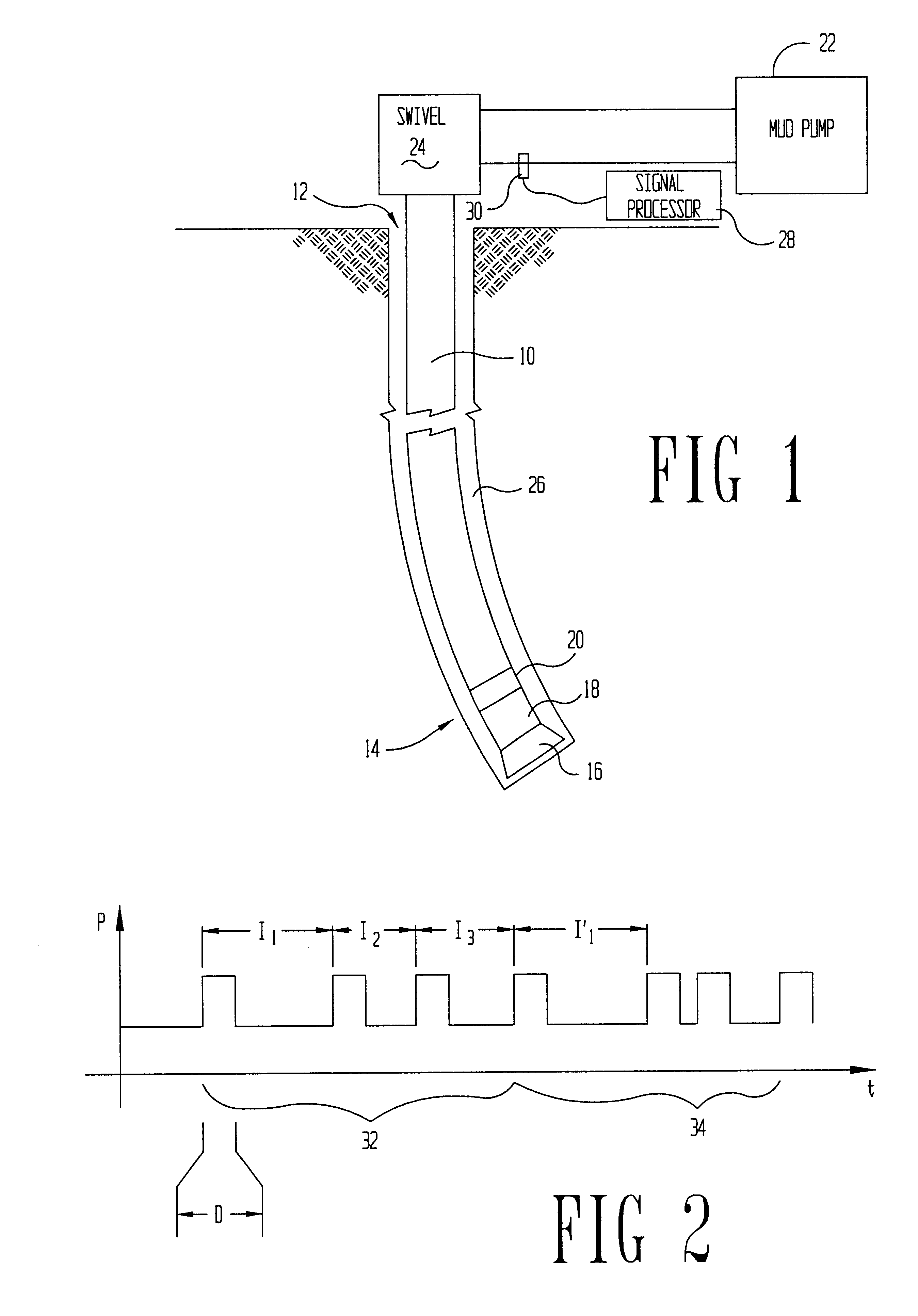
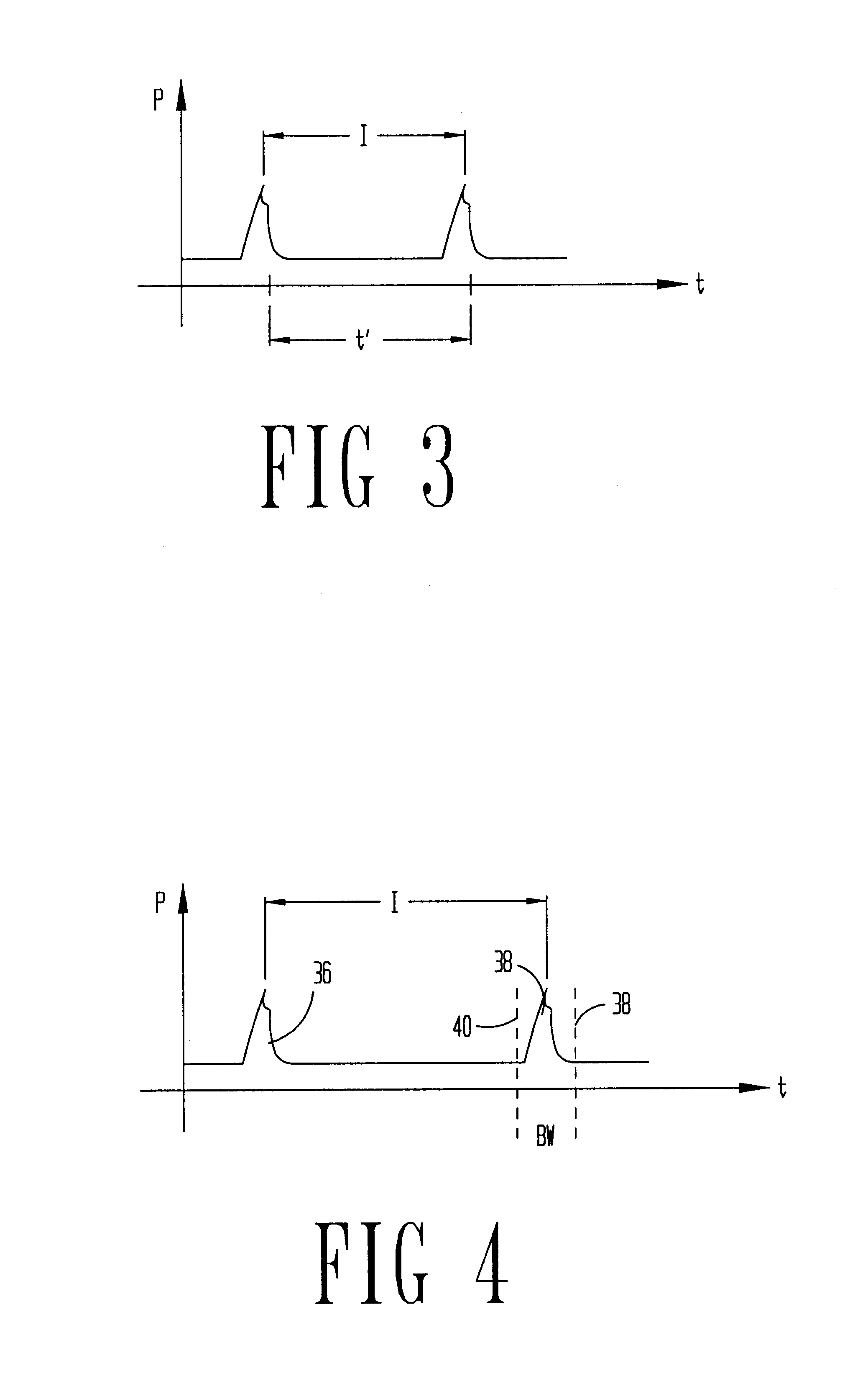
A mud pulse telemetry technique that uses a number of bits per interval based on parameters of the pulse position modulation system in order to reduce data transfer time in a pulse position modulation system. More particularly, depending on parameters of the pulse position modulation such as the minimum-time and the bit-width, it may be possible to decrease overall transmission time by splitting values having a larger number of bits into multiple transmissions with each transmission having a smaller number of bits.

Description

Not applicable.1. Field of the InventionThe embodiments disclosed in the specification are directed to increasing the efficiency of data transfer in pulse telemetry systems. More particularly, the embodiments disclosed are directed to an encoding system that increases the bit transfer rate in mud pulse telemetry systems.2. Background of the InventionMud pulse telemetry is used to communicate information from downhole devices to the surface during drilling. This information may include measuring-while-drilling (MWD) information (direction and orientation of the bottomhole assembly, downhole pressure, borehole characteristics, and the like), as well as logging-while-drilling (LWD) information regarding the surrounding formation (electromagnetic wave resistivity, gamma ray, density, and the like).The communication medium for mud pulse telemetry is the column of drilling fluid within the drill string. The primary purpose of the drilling fluid, however, is not to facilitate data communic...

Claims


Application Information

Patent Timeline
Patent Type & Authority Patents(United States)
IPC IPC(8): G01V11/00
CPCG01V11/002
Inventor SUN, CILIMARSH, LABAN M.PILLAI, BIPIN K.
Owner HALLIBURTON ENERGY SERVICES INC
Learn More