Cyclic time averaging for machine monitoring

a technology of machine monitoring and cyclic time averaging, which is applied in the direction of testing/monitoring control systems, instruments, force/torque/work measurement apparatus, etc., can solve problems such as machine failure, significant financial losses, and fatal injury and processing system backup

Inactive Publication Date: 2004-09-07
SKF USA INC
View PDF7 Cites 23 Cited by
  • Summary
  • Abstract
  • Description
  • Claims
  • Application Information

AI Technical Summary

Problems solved by technology

Despite increasingly efficient maintenance programs, at any time some percentage of the machines develop defects that are likely to lead to machine failure.
For example, machines having moving parts (e.g., bearings) experience constant friction that results in wear.
It is known that bearing failures are a major cause of motor faults.
Bearing damage due to wear may not be apparent, however, absent gross damage or failure of the motor because the bearing's wear site is likely concealed in the motor's assembled state.
Unscheduled plant shutdowns can result in considerable financial losses.
Failure of high performance machinery can lead to fatal injury and processing system backup.

Method used


Image

  • Cyclic time averaging for machine monitoring
  • Cyclic time averaging for machine monitoring
  • Cyclic time averaging for machine monitoring

Examples


Embodiment Construction

Embodiments of the invention will now be described with reference to the accompanying figures, wherein like numerals refer to like elements throughout. The terminology used in the description presented herein is not intended to be interpreted in any limited or restrictive manner, simply because it is being utilized in conjunction with a detailed description of certain specific embodiments of the invention. Furthermore, embodiments of the invention may include several novel features, no single one of which is solely responsible for its desirable attributes or which is essential to practicing the inventions herein described.

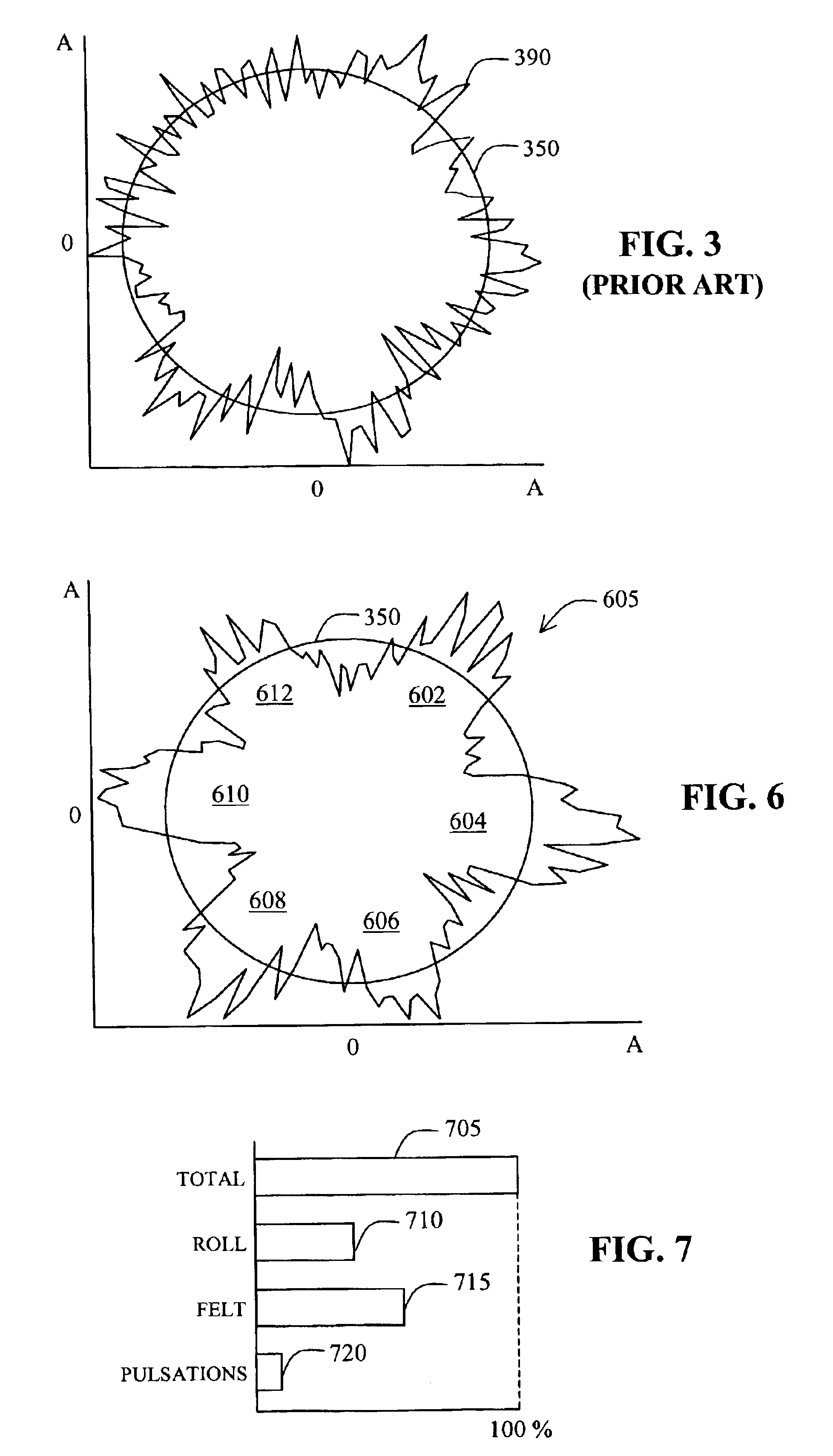
In general terms, embodiments of the invention concern a cyclic time averaging ("CTA") method and a related system for deriving an averaged waveform suitable for a profile plot display (see FIG. 6), which depicts energy contributions using time-domain data in a circular diagram limited to one period of the phenomenon under consideration. In some embodiments, CTA us...


PUM

PropertyMeasurementUnit
frequencyaaaaaaaaaa
frequencyaaaaaaaaaa
timeaaaaaaaaaa

Abstract

The condition of a machine is monitored with cyclic time averaging, a technique of allocating vibration energy to particular sources in a complex signal. The cyclic time averaging method is directed at processing time-domain vibration data of the machine to produce an averaged time waveform over a selected cyclic time period. Utilizing cyclic time averaging, the systems and methods analyze machine vibration signals to detect and evaluate specific sources of enemy contribution to the vibration energy of the machine. It is not necessary to employ a triggering signal to obtain the averaged time waveform.

Description

1. Field of the InventionThe invention generally relates to systems and methods for monitoring the condition of a machine. More particularly, the invention concerns systems and methods for analysis of machine vibration signals to detect and evaluate specific sources of energy contribution to the vibration energy of the machine.2. Description of the Related ArtIt is common for industrial and commercial facilities to operate a large number of machines concurrently, many of which may cooperate in a large interdependent process or system. Despite increasingly efficient maintenance programs, at any time some percentage of the machines develop defects that are likely to lead to machine failure. For example, machines having moving parts (e.g., bearings) experience constant friction that results in wear. It is known that bearing failures are a major cause of motor faults. Bearing damage due to wear may not be apparent, however, absent gross damage or failure of the motor because the bearing...

Claims


Application Information

Patent Timeline
Patent Type & Authority Patents(United States)
IPC IPC(8): G01H1/00
CPCG01H1/003G05B23/0235
Inventor BOERHOUT, JOHANNES I.
Owner SKF USA INC
Why Eureka
Try Eureka