
Special flexible fixture for machining vibration control of complex thin-wall blade parts

A part processing and vibration control technology, which is applied in the direction of manufacturing tools, metal processing equipment, metal processing machinery parts, etc., can solve the problems that the cutting system cannot compensate for time-space changes and does not have adjustable characteristics, so as to increase the process stiffness and damping characteristics, high-frequency response performance, and the effect of improving machining accuracy

Pending Publication Date: 2020-01-07
HENAN POLYTECHNIC UNIV
View PDF2 Cites 16 Cited by
  • Summary
  • Abstract
  • Description
  • Claims
  • Application Information

AI Technical Summary

Problems solved by technology

However, the external output damping of this device is a fixed value. When processing thin-walled parts, the geometric structure and quality of the workpiece are changing with the material removal, which will cause the selected initial cutting parameters to fail to make the cutting process stable. However, the methods proposed in the literature are not adjustable, and cannot compensate for the temporal and spatial changes in the dynamic characteristics of the cutting system caused by material removal, and cannot avoid the occurrence of Instability such as flutter

Method used


Image

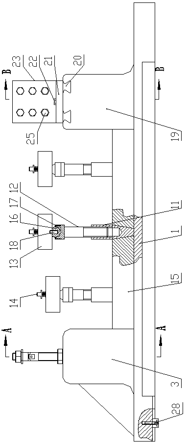
  • Special flexible fixture for machining vibration control of complex thin-wall blade parts
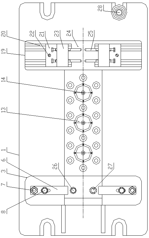
  • Special flexible fixture for machining vibration control of complex thin-wall blade parts
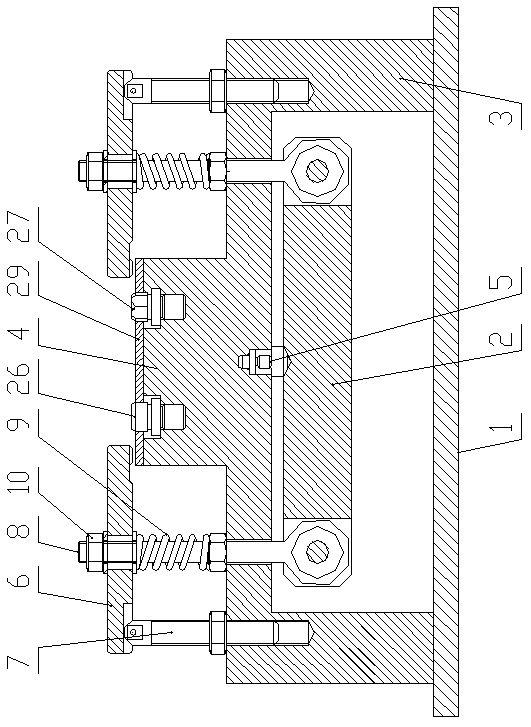
  • Special flexible fixture for machining vibration control of complex thin-wall blade parts

Examples


Embodiment Construction

[0028] The implementation of the present invention will be illustrated by specific examples below, and those skilled in the art can easily understand other advantages and effects of the present invention from the content described in this specification. It should be noted that the structures, proportions, sizes, etc. shown in the drawings of this specification are only used to match the content disclosed in the specification, for those who are familiar with this technology to understand and read, and are not used to limit the conditions for the implementation of the present invention , so it has no technical substantive meaning, and any modification of structure, change of proportional relationship or adjustment of size shall still fall within the scope of the disclosure of the present invention without affecting the functions and objectives of the present invention. within the range covered by the technical content. At the same time, terms such as "upper", "lower", "left", "r...


PUM


Abstract

The invention discloses a special flexible fixture for machining vibration control of complex thin-wall blade parts. The special flexible fixture comprises a bottom plate, wherein a double-pressing plate linkage mechanism, an auxiliary supporting mechanism and a multi-point ejector pin clamping mechanism are sequentially arranged on the bottom plate from left to right; a plurality of the auxiliarysupporting mechanisms are provided; the height of each auxiliary supporting mechanism is adjustable. According to the special flexible fixture, the multi-point ejector pin clamping mechanism is adopted, and the problem that the thin-wall part of the free curved surface is difficult to clamp is solved.; on the basis of positioning and clamping, a magneto-rheological material with controllable performance is adopted, small displacement sensitivity, high output damping and good high-frequency response performance of cutting machining are adopted to control the damping support, so that the rigidity of the machining process is enhanced, and the machining precision of the workpiece is improved; and when a similar part of another size is machined, under the condition that the layout condition ofthe original fixture is not changed, the magnetic rheological damper with different sizes can be replaced by adjusting the distance between the multi-point clamping mechanisms, so that the clamping of the existing workpiece can be met.

Description

technical field [0001] The invention belongs to the technical field of machining complex thin-walled parts, and in particular relates to a special flexible fixture for vibration control of complex thin-walled blade parts. Background technique [0002] Aeroengines are sophisticated and complex high-end equipment, and their parts work in harsh environments such as high temperature, high pressure, and high speed. In order to meet their performance requirements such as high performance and high reliability, high-precision machining of aeroengine parts is required. In the aviation industry, a large number of thin-walled parts with complex free-form surfaces are used to achieve the goals of weight reduction, compact structure, and excellent overall performance. However, thin-walled parts have the characteristics of complex structure and poor rigidity. At the same time, there are non-uniform clamping force and clamping residual stress in the application process of the fixture, and ...

Claims


Application Information

Patent Timeline
Patent Type & Authority Applications(China)
IPC IPC(8): B23Q3/00B23Q11/00B23Q3/06B23Q1/76
CPCB23Q3/00B23Q11/00B23Q3/06B23Q1/76B23Q3/062B23Q3/063
Inventor 马俊金李云飞童景琳牛赢王楚赵波
Owner HENAN POLYTECHNIC UNIV
Learn More